


The Ping Pong Robot to Return a Ball Precisely
- Robotics
- AI
- Optimization
- Kinetic analysis
We are developing a ping-pong robot “FORPHEUS” that can play table tennis with humans representing the harmony between humans and machines.
In order to accurately return the ping-pong ball, the robot must perform the following tasks: predicting the trajectory of the ball before and after hitting the racket and determining the movement of the racket (velocity and direction to return the ball).
The spin of the ball must be taken into account in those tasks because it has a major impact on the ball trajectory and the racket movement. However, we could not consider the effect of the ball spin because a standard industrial camera (80 fps) which doesn't have sufficient flame rate is being used.
Therefore, we propose a new method to estimate the rotational velocity of the ball with a standard flame rate camera and how to improve the accuracy of the return point. For the sake of the proposed method, the ping-pong robot can return 36.5 cm more accurately than the conventional one. As a result, human-machine harmony increases, especially for ping-pong beginners.
1. Introduction
We have been working on the development of the ping-pong robot FORPHEUS since 2013. This robot can interact with people in ping-pong rallies by means of which we present the concept of harmony between human and machines that OMRON envisions for future relationship between human and machines1),2). The phrase “harmony between human and machines” in our sense assumes the progress of the relationship of machines and human. This concept envisions an evolutionary relationship between human and machines that evolves as follows: from a stage where machines perform tasks in place of human to another stage where machines and people work in collaboration with each other, and further into yet another stage where machines understand the condition or behavior of human and help human draw out their potential strength. Broadly speaking, our robot is required to have the following two functions to achieve a successful realization of this concept:
- A function that recognizes the skills of human players and devises a strategy for keeping a rally going with a slight lead over the human player
- Return shots precise and accurate enough to realize this strategy
For a robot to play table tennis, it takes high-speed, highprecision ball sensing technology, racket motion planning technology, and high-precision control technology. Therefore, this has been a study theme in the field of robotics for a long time3). In recent years in particular, racket motion planning technologies have been vigorously studied for robots to hit return shots with high precision. In a table tennis game, a spinning ball is hit back and forth. Therefore, examples of approaches proposed so far include aerodynamic or impact model-based approaches taking the rotation speed effect into consideration4),5) and learning-based approaches focusing on the cause-and-effect relation between the racket motion and the ball trajectory6). In addition, there are also approaches proposed to realize human-like flexible racket motions. Examples of approaches proposed so far include reinforcement learningbased approaches involving motions generated through direct human teaching to improve the accuracy of the return shot7) or optimal control problem approaches with torque optimality included in constraint conditions8).
Our ping-pong robot system is based on reference4) and is built without any special equipment but with general industrial equipment for factory use, including mainly our own products, aiming to demonstrate the feasibility of the man-machine harmony concept. Therefore, the methods proposed in references4),9) for rotation speed measurement using an ultra-high speed camera (900 fps) were difficult to apply to our system equipped with the general industrial camera we adopted (80 fps). As a result, our conventional ping-pong robot made trajectory predictions without taking the ball rotation speed into consideration and kept hitting back inaccurate shots at the target positions. Moreover, in racket motion planning for return shots, neither reference 4 nor our conventional ping-pong robot considered the ball rotation speed. Hence, both failed to make racket motions coordinated with the rotation speed and ended up with a further drop in accuracy of the return shot.
On the other hand, the recognition speed of the human eye is said to be similar to that of cameras in general use (80 fps). Human table tennis players, however, can hit return shots with high accuracy by selectively using different types of strokes or different types of shots according to the ball rotation speed. This is because they can estimate the rotation speed from the ball trajectory and move the racket based on the estimated rotation speed. Then, we devised a new method for estimating the rotation speed from the ball trajectory using an industrial camera.
This paper proposes a ping-pong robot system capable of hitting return shots with high accuracy. This robot system was developed with the ball rotation speed taken into consideration to demonstrate the ability to sustain a rally with a slight lead over the human player, which is the latter of the two functions for realizing man-machine harmony. The adoption of the rotation speed estimation method has enabled our robot system to hit return shots with high accuracy by predicting both the incoming and outgoing ball trajectories and by allowing for the rotation speed in the racket motion planning for return shots.
In what follows, Chapter 2 presents the system configuration of our ping-pong robot, followed in Chapter 3 by the description of the principle of return-shot hitting by the pingpong robot. Chapter 4 presents the conventional system used without rotation speed estimation. Chapter 5 explains our proposed ball rotation speed estimation technology. Chapter 6 examines its effectiveness, and finally, Chapter 7 concludes with future prospects.
2. System configuration of the ping-pong robot
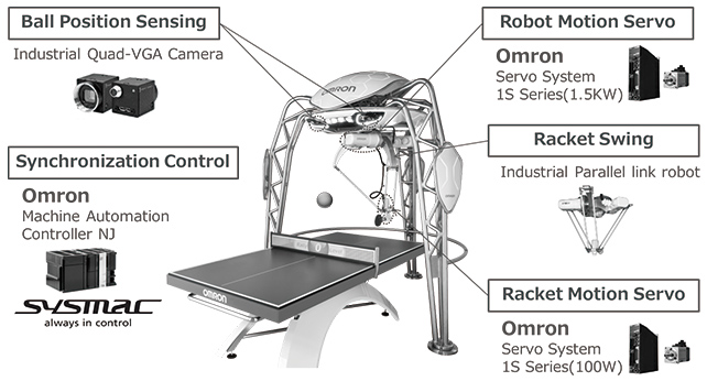
Fig. 1 shows the system configuration of our ping-pong robot. The ping-pong robot under development at OMRON uses equipment for use in general industrial applications such as industrial robots. The camera installed on it for measuring the three-dimensional position of the ball is an 80-fps, Quad-VGA industrial camera intended for purposes such as product inspection. Moreover, this robot is based on a parallel link robot used in applications such as rapid workpiece transfer. Our robot is equipped with two servo systems both designed to drive belt conveyors: one is used as the drive unit for the robot and the other as the drive unit for the racket. A programmable logic controller (PLC) is used to update the position control command at 1 ms intervals.
3. Principle of return-shot hitting by the pingpong robot
This chapter describes the principle of return-shot hitting by the ping-pong robot.
3.1 Incoming ball trajectory prediction
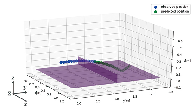
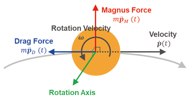
Fig. 2 shows the conceptual image of incoming ball trajectory prediction. This trajectory prediction is performed to predict the ball trajectory leading up to near the robotʼs hitting point based on the ball position observed at time after rebounding. It is known that in general, a ball shows not a simple parabolic motion but a non-linear motion due to aerodynamic characteristics such as the drag force associated with the ball velocity or the Magnus force associated with the rotation speed3). Fig. 3 shows the aerodynamic force on the ball. At this point, the ball behaves according to the dynamic model expressed by Equation (1):
-
 (1)
(1)
where  ,
,  , and
, and  stand, respectively, for the ball position [m], the ball velocity [m/s], and the ball acceleration [m/s2] at timein the coordinate system shown in Fig. 2. Meanwhile,
  stands for the ball rotation speed [rad/s]. Here, the x-, y-, and z-axes are as shown in Fig. 2. In other words, if the ball moving from the human player toward the robot is under rotation with a rotation speed
  of -100 [rad/s] around the x-axis, the ball is with a strong topspin on it. While
  stands for the drag force on the ball and occurs in a direction opposite to the moving direction of the ball,
  stands for the Magnus force on the ball and occurs in the direction of the outer product of the ballʼs moving direction and rotation axis. Finally,
  ,
,  , and
, and  stand, respectively, for the mass of the ball [kg], the drag constant, and the Magnus constant. Equation (1) is a second order non-linear ordinary differential equation for the ball position. The trajectory can be predicted by repeatedly solving this ordinary differential equation.
3.2 Outgoing ball trajectory prediction
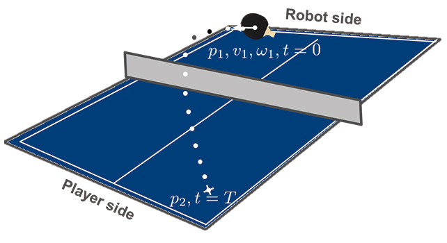
In outgoing ball trajectory prediction from the ping-pong robot, the trajectory of the ball is calculated back from its target position to determine its velocity immediately after the return shot. Fig. 4 shows the conceptual image of outgoing ball trajectory prediction. The hitting point position at the moment of the return shot,  =
=  , the target position for outgoing balls,
  =
=  , and the rotation speed immediately after the return shot,=
  , are set as the boundary value conditions to determine the outgoing ball velocity,
  =
=  . This paper, however, assumes that the outgoing ball rotation speed remains unattenuated. Let us assume here that the time the outgoing ball needs to reach the target position is= T.
can be obtained by solving the inverse problem of the dynamic model of the ball given by Equation (1).
3.3 Racket motion planning for return shots
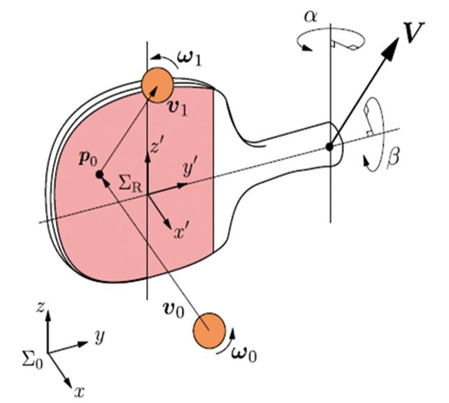
Fig. 5 shows the conceptual image of racket motion planning for return shots. In racket motion planning for return shots, the racket velocity  [m/s] and the racket posture
  ,
,  [rad] at the moment of the return shot are determined to allow the robot to hit a return shot at the ball velocity determined based on the outgoing ball trajectory prediction.
The formulation for a return shot hit with the racket can be given by the racket-ball impact model expressed as in Equation(2):
-
 (2)
(2)
where  ,
,  , , and stand, respectively, for the velocity and rotation speed of incoming and outgoing balls, while stands for the racket velocity at the moment of the return shot. Meanwhile,
  stands for the rotation matrix to be transformed from the coordinate system
  shown in Fig. 2 into the racket coordinate system
  in Fig. 5, while
  ,
,  ,
,  , and
, and  stand for the mutual transformation matrix of the velocity and rotation speed of incoming and outgoing balls. The former and the latter are expressed by the following equations:

where  stands for the coefficient of restitution between the ball and the racket, while
  and
and  stand respectively for the coefficients of friction caused by the relative velocity and rotation speed between the ball and the racket. The velocity and posture of the racket at the moment of the return shot can be obtained by solving Equation (4) for , , and . By solving the problems in Sections 3.1 to 3.3, the ping-pong robot can hit return shots to a target position with high accuracy.
4. Conventional system
This chapter describes the return shot that the ping-pong robot in Sections 3.1 to 3.3 hits without taking the rotation speed into consideration (![ω = [0,0,0]T](/global/en/assets/img/technology/omrontechnics/vol51/016/i_34.svg) ) similarly to the conventional system.
) similarly to the conventional system.
4.1 Incoming ball trajectory prediction without the rotation speed taken into consideration
When , the dynamic model of the ball will be given by Equation (3):
-
 (3)
(3)
This dynamic model is repeatedly solved to perform trajectory prediction without the rotation speed taken into consideration.
4.2 Outgoing ball trajectory prediction without the rotation speed taken into consideration
Assuming that holds for the dynamic model of the ball, the following approximate dynamic model proposed in Reference 4 was used for analytical solution:
-
 (4)
(4)
where  . Equations (4) allows analytical solution of the hitting point position, = , and the target position for outgoing balls, = , as boundary value conditions. The outgoing ball rotation speed, = , can be obtained by Equations (5):
-
 (5)
(5)
4.3 Racket motion planning for return shots without the rotation speed taken into consideration
Let the rotation speed in Equation (2) be =  =
= ![[0,0,0]T](/global/en/assets/img/technology/omrontechnics/vol51/016/i_37.svg) . Then, the following holds:
. Then, the following holds:
-
 (6)
(6)
The velocity and posture of the racket for when the robot hits a return shot can be obtained by solving Equation (6) for ![V(=[Vx,Vy,Vz]T)](/global/en/assets/img/technology/omrontechnics/vol51/016/i_38.svg) , , and . Note, however, that for the three equations for the three-dimensional coordinate system, there are five variables to be obtained. Hence, they cannot be obtained uniquely. Therefore, to solve Equation (6), two constraint conditions
, , and . Note, however, that for the three equations for the three-dimensional coordinate system, there are five variables to be obtained. Hence, they cannot be obtained uniquely. Therefore, to solve Equation (6), two constraint conditions  = 0 and = 0 are imposed on their respective corresponding variables: standing for the velocity of upward racket swing, which is a motion relatively insignificant to the attempt to improve the accuracy of position of the return shot; and , the elevation angle of the racket. The above numerical calculations are thus used to enable the robot to keep a rally going with the human player under conditions that do not take the rotation speed into consideration.
5. Proposed system
This chapter proposes a ball rotation speed estimation method, an incoming and outgoing ball trajectory prediction method with the rotation speed taken into consideration, and a racket motion planning method for the robot to hit return shots to the target position with higher accuracy.
5.1 Incoming ball trajectory prediction with the rotation speed taken into consideration
To perform trajectory prediction with the rotation speed taken into consideration, the dynamic model including the Magnus term ({ ×}) in Equation (1) must be repeatedly solved. This section then explains a method that does not measure but estimates the rotation speedof the ball hit back by the human player at time .
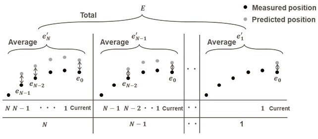
Fig. 6 shows the conceptual image of the ball rotation speed estimation method. For a total of  number of the ball measurement points photographed from after rebounding up to the current time, Equation (1) is used to obtain the predicted positions after the target measured position. Then, the sum of the mean errors from the actual measured positions is used as an evaluation function
  to solve an optimization problem that obtains the rotation speed where the evaluation function is minimized.
The evaluation function is given as Equation (7):
-
 (7)
(7)
Where  (
( = 1,2 ...
  -1) stands for the errors between the predicted and actual measured positions up to the current time, which were estimated at the th prior measured position from the current time while
  ( = 1,2 ... ) stands for the mean of all from the -1th prior measured position to the current position. The sum of this number of mean error is the evaluation function . Trajectory prediction with spinning taken into consideration can be performed by estimating the rotation speedat which this evaluation function is minimized.
Let us explain here the reason for the adoption of this method. A rotation speed is obtained by minimizing the difference between measured and predicted positions. This means that the accuracy of an estimated ball velocity is significantly affected by the accuracy of the rotation speed. This is because when obtaining predicted positions, Equation (1) is repeatedly solved using ball velocity as one of the initial conditions. Moreover, because ball velocity is obtained from the forward difference between two measured positions, the accuracy of ball velocity is dependent on the accuracy of the measured positions. Therefore, the former can be improved by adopting a rotation speed that minimizes the errors of predicted positions estimated from all past measured positions.
5.2 Outgoing ball trajectory prediction with the rotation speed taken into consideration
Let us first consider how to determine the rotation speed of the ball hit back by the ping-pong robot. To determine the outgoing ball rotation speed means to determine the type of shot the robot uses to hit the ball back. For example, when the rotation speed is set to  > 0, the robot will return a topspin shot. Alternatively, if |
 | > 0, the robot will return a sidespin shot. Thus, the setting of will be determined based on the type of return shot the robot is expected to hit.
Next to be considered is solving the inverse problem of the dynamic model of the ball. Equation (1) is a non-linear ordinary differential equation and is therefore difficult to solve analytically. Accordingly, a numerical solution should be sought. Assume that  is the predicted position of the outgoing ball after T seconds from the time the ball hit back by the pingpong robot with velocity reaches the target position for outgoing balls. Then obtain the velocity that minimizes the error between the target position for outgoing balls, , and the predicted position of the outgoing ball, . Here, the evaluation function is formulated as Equation (8):
-
 (8)
(8)
Thus, an accurate return shot velocity can be obtained by obtaining that minimizes this evaluation function .
5.3 Racket motion planning for return shots with the rotation speed taken into consideration
By obtaining the incoming ball velocity immediately before a return shot as in Section 5.1 and the return shot velocity as in Section 5.2 and substituting these velocities into Equation (4) to determine all three variables, , , and , the robot can hit return shots to the target position with high accuracy.
6. Verification experiment
This chapter presents the verification test results for the effectiveness of the system proposed in Chapter 5.
6.1 Outline and results of the experiment
The errors between the actual landing points of the balls hit back by the ping-pong robot and the target position for outgoing balls were compared with those encountered with the conventional system to verify the effectiveness of the proposed system. For both the proposed and conventional systems, missed return shots (air shots, faulty shots hit by the edge of the racket, etc.) due to the influence of trajectory prediction errors were deemed as outliers.
Fig. 7 shows the verification results. This figure compares the proposed and conventional systems in terms of the actual landing points of approximately 100 balls that the robot hit toward the target position for outgoing balls ( = [0.6,0.5,0] ). For the proposed system, the outgoing ball rotation speed was set as = [50,0,0]. As shown in Fig. 7, the proposed system returned more accurate shots to the target position for outgoing balls. It should be noted here that
  = 0 corresponds to the edge of the table and hence that the < 0 area means the area beyond the table.
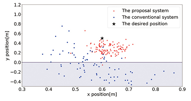
When the distances between the target position for outgoing balls and the landing points of the actual shots are regarded as errors, the conventional system showed a mean error of 59.0 cm with a standard deviation of 23.3 cm. Meanwhile, the proposed system showed a mean error of 22.5 cm with a standard deviation of 0.9 cm. These results reveal that the latter has been improved in terms of the accuracy of the return shot relative to the target position for outgoing balls.
To keep a rally going with a beginner to help with skillbuilding (for example, by guiding the person to switch between forehand and backhand strokes or by steadily inviting the person to return forehand shots), the robot is required, at minimum, to have performance good enough to hit balls alternately to its left and right without making missed shots. In other words, taking into consideration the size of the table (152.5 cm width, 137.0 cm long to the net), the return shots hit by the robot must fall within a maximum mean error of approximately 30 cm. Then, from the experiment results, we can conclude that the proposed system has the performance sufficient to sustain a rally with a beginner and help to improve ping-pong skills.
6.2 Discussion
The robot system we proposed herein can hit return shots taking into consideration the rotation speed of the ball and, hence, shows an improved accuracy of the return shot relative to the target position for outgoing balls. Yet, the proposed system is still not free from errors relative to the target position for outgoing balls. The factors considered responsible for this are listed below. These challenges must be solved for this system to sustain skill-building rallies with intermediate table tennis players (average player level).
- (i) Ball position measurement accuracy;
- (ii) Accuracy of the racket-ball impact model; and
- (iii) Motion control performance of the robot
Challenge (i) demands further improvement in measurement accuracy. This has emerged because the accuracy of the rotation speed estimation based on Equation (7) is affected by the errors of ball position measurements. With regard to Challenge (ii), this paper uses a linear model given by Equation (2) to represent the collision between the ball and the racket. In reality, however, the racket is faced with rubber. Therefore, the collision between the ball and the racket occurs as a non-linear phenomenon. As a result, a linear model suffers errors in the ball velocity at the moment of the return shot relative to the target value. Finally, Challenge (iii) relates to the constraints of the limited range of motion or acceleration of the robot. Because of these constraints, the target racket velocity may not be met. Therefore, measures such as a review of the structure of the robotʼs hand tip must be implemented to improve the current mechanism to achieve the required velocity.
7. Summary
In this paper, we proposed a ping-pong robot system that has been realized by the combination of the following three methods: a method of rotation speed estimation using 80 fps industrial cameras, thereby providing the foundation for the following two methods; a method of incoming and outgoing ball trajectory prediction; and a racket motion planning method for the robot to hit return shots to the target position with higher accuracy.
We hope to implement more advanced ping-pong skills in our robot. Hence, we will solve the challenges presented in Section 6.2 to develop technologies that enable our robot to hit back various types of shots with higher accuracy and to make strategically selective use of such types of shots to suit the level of the human player. Moreover, we will develop not only ballmotion but also human-motion measurement technologies for our robot to perform rotation speed estimation and trajectory prediction from the human playerʼs pre-shot motion before the player can actually hit the ball―toward the realization of a robot with more advanced ping-pong skills. Building on these technologies, we would like to attract a wider audience to our vision of harmony between human and machines that leads people to achieve further personal growth.
References
- 1)
- Yamada, K.: Robot Table Tennis Tutor as an Example of “Harmony between Human and Robot”. The Journal of the Institute of Electrical Engineers of Japan. 2017, Vol.137, No.2, p.81-84 (in Japanese).
- 2)
- Nisina, Y.; Suwa, M.; Kawade, M. Application of Image Sensing and AI Technologies to Table Tennis Robots, O plus E . 2017, Vol.39, No.12, p.1195-1200 (in Japanese).
- 3)
- Anderson, R.L. A Ping-Pong Player: Experiment in Real-Time Intelligent Control. MIT Press, 1988.
- 4)
- Liu, C.; Hayakawa, Y.; Nakashima, A.: Racket Control for a Table Tennis Robot to Return a Ball. SICE Journal of Control, Measurement, and System Integration. 2013, Vol.6, No.4, p.259-266.
- 5)
- Zhao, Y.; Xiong, R.; Zhang, Y. Model Based Motion State Estimation and Trajectory Prediction of Spinning Ball for Ping-Pong Robots using Expectation-Maximization Algorithm. Journal of Intelligent & Robotic Systems. 2017, Vol.87, No.3-4, p. 407-423.
- 6)
- Wang, Q.; Sun, Z. Trajectory Identification of Spinning Ball Using Improved Extreme Learning Machine in Table Tennis Robot System. 2015 IEEE International Conference on Cyber Technology in Automation, Control and Interlligent Systems. 2015, p.551-554.
- 7)
- Huang, Y.; Scholkopf, B.; Peters, J. Learning optimal striking points for a ping-pong playing robot. IEEE Internatinal Conference on Intelligent Robots and Systems. 2015, Vol.2015-Decem, p.4587-4592.
- 8)
- Koç, O.; Maeda, G.; Peters, J. Online optimal trajectory generation for robot table tennis. Robotics and Autonomous Systems. 2018, Vol.105, p.121-137.
- 9)
- Liu, C.; Hayakawa, Y.; Nakashima, A. An on-line algorithm for measuring the translational and rotational velocities of a table tennis ball. 2011 IEEE International Conference on Robotics and Biomimetics. 2011, Vol.5, No.4.
The names of products in the text may be trademarks of each company.