


Development of super high-speed CT X-ray automatic inspection system
- CT
- X-ray
- Automatic inspection system
- Inline
- Solder inspection
In the board mounting industry, there are an increasing number of parts and boards that are difficult to be insepected with AOI because solder is invisible. And high quality requirements such as bonding strength of the automobile industry and full surface inspection of the solder are increasing. In order to respond to these needs, we introduce the latest technology for achieving within the given on-line takt time required which was the most problematic task in CT type X-ray automatic inspection equipment.
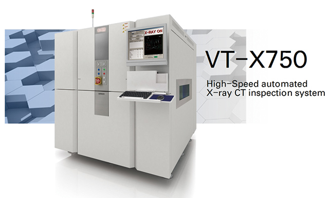
For continuous imaging technology, highly accurate positioning control and high speed image sensing are required. With this technology, the VT-X750 realized a significant improvement in takt time by more than twice as compared with the conventional machine, realized low radiation inspection and made the first in-line full surface inspection possible in the industry. Based on a new platform, we introduce Omron’s AXI (Automated X-RAY Inspection system) that brings about a safer and more secure world while evolving with the times.
1. Introduction
In recent years, there have been remarkable technological advancements achieved in electric vehicles (EVs) and advanced driving assistant systems (ADASs), including automated driving. Therefore, the world of circuit board mounting is heading towards further densification. At the same time, more and more parts and circuit boards with visually inaccessible soldered joints are coming into use, causing difficulties in visual inspection. Typical examples include fillet-less chips and ball grid arrays (BGAs) with solder joints arranged on the underside of the package. In the market, the automotive industry imposes particularly stringent quality assurance requirements. Suppliers are often required to perform in-line full surface inspection inspections of circuit boards rather than sampling inspections and to measure solder shapes and inspect down to bonding strength. In addition, there is also the problem of line worker shortages, which are partly responsible for the current rapid increase in demand for high-precision, high-quality automated inspections. Hence, events in the mounting industry, such as circuit board quality issues and production line stoppages, pose potential serious risks to customers. An outflow of defective circuit boards would immediately lead to a crisis that could threaten the security of people and society. Accordingly, it has become more important than before to provide a mechanism that prevents or precludes any outflow of defective circuit boards to the market to help our customers improve their product quality. In response to such social trends, Omronʼs automated X-ray inspection (AXI) system has found its way into wide use in surface mount technology (SMT) production lines as a machine capable of inspecting visually inaccessible items, such as solder joints provided on the underside of parts. Because of the problem with takt time, however, an conventional model has been used mainly for offline sampling inspections or for inline inspections of key parts only. This paper presents an outline of the technologies employed for the automated inline X-ray CT inspection system VT-X750 (Fig. 1) to improve this problem significantly and achieve a high speed sufficient for inline use in circuit board mounting processes in the automotive industry, thereby allowing quality assurance of a lot of circuit boards.
2. CT-based AXI for achieving high image quality
2.1 Comparison of X-ray diagnostic imaging methods
The major types of X-ray-based diagnostic imaging methods include2D X-RAY.
2D X-RAY, tomosynthesis, and computed tomography (CT) methods. The characteristics of these methods are as follows:
The 2D X-RAY method is used to obtain one image per shot with an X-ray source, a workpiece, and an X-ray camera arranged vertically (Fig. 2). The image projected by this method is two-dimensional (2D) data. While capable of image acquisition in a shorter acquisition time, this method is inferior to the other methods in terms of image quality because the amount of data that it handles is small (Fig. 3).
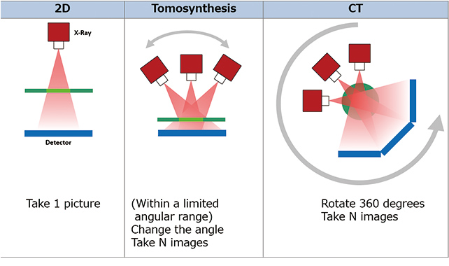
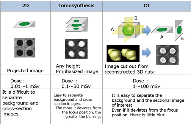
The tomosynthesis method is used to obtain an N number of images of a workpiece in a relative position to an X-ray source/X-ray camera within a limited angular range. This method allows acquisition of tomographic images with the desired heights highlighted (Fig. 3). Though time-consuming for image acquisition than the 2D X-RAY method, this method allows faster image acquisition than the CT method. This method is superior to the 2D X-RAY method in terms of image quality. If, however, captured far from the focus position of the X-ray source or the X-ray camera, tomographic images tend to end up with a blurrier image quality than that of CT images (Fig. 3).
The CT method is used to obtain an N number of images of a workpiece in a relative position to an X-ray source/X-ray camera during a 360-degree rotation and to reconstruct them into three-dimensional (3D) data (Fig. 2). This method handles a larger volume of data than the other methods and hence provides the best image quality. Its strength is that it allows the extraction and use of not only horizontal planar direction data but also height direction data from the restructured 3D data. Even if captured far from the focus position of the X-ray source or the X-ray camera, a tomographic image will have a clear, low-blur image quality. On the other hand, however, this method takes more time for image acquisition and hence usually delivers a higher dose to the workpiece (Fig. 3).
2.2 OMRON’s AXI
We have adopted a CT method that can identify the desired points in 3D data and perform image-based diagnosis of these points to accurately inspect the shape of each solder joint surface. Since its release in 2009, the automated inspection system of the VT-X700 using the CT imaging method has met a wide range of customersʼ inspection needs, including mainly BGA void inspection needs. Our AXI consists of various technical components and takes advantage of the CT method, free from circuit board underside restrictions, on the basis of the rich knowledge earned through experience in visual inspection systems, thus allowing high-precision inspections. Its major technical components are hardware capable of safe, robust, and high-precision sensing and software that enables high-speed control with excellent responsiveness. The hardware consists largely of mechanical, electrical, and imaging components. Therefore, the design parameters, such as electromechanical safety, shielding, axis motion accuracy, control responsiveness, image quality, and imaging rate, play an important role in ensuring system performance. The software part of the system consists of assembly optimizer software for machine difference corrections, a main application for inspection program development, a reconstruction process for turning captured images into 3D data, and an algorithm used to perform the inspections of the obtained 3D data. These technical components are complicatedly related to each other. For highprecision, high-speed inspections, therefore, these mutually related components must work seamlessly and precisely in each function module. Particularly important for high-quality CT image acquisition, which is the core of this technology, is the basic performance of the imaging devices, high-precision geometry design and control, and robust correction processing and inspection algorithms.
2.3 Basic performance of imaging devices (FPD and X-ray source)
The flat panel detector (FPD) is a camera that first converts X-rays into light via a fluorescent emitter called the scintillator and then light into electrical signals in order to obtain digital images. Through pixel-by-pixel loading, images with high sharpness and high sensitivity can be obtained. Our system is equipped with a complementary metal oxide semiconductor (CMOS) type of FPD to obtain high-definition images of the object. Each parameter is designed to obtain images with contrast optimized to suit the part or object to be isolated for inspection purposes.
X-ray sources fall largely into two types: one called the open tube and the other called the closed tube. An open-type X-ray source has the following disadvantages: it must be installed along with a vacuum pump and other associated equipment outside it, high running cost due to such factors as a short-life filament, and the radiation source itself has a large weight. Meanwhile, in the case of a closed tube, the X-ray generator is constantly kept in a vacuum in a glass hermetic container. Hence, this type of radiation source features a compact body and does not need installation of a pump outside its tube. Adopted for installation on our system is a micro-focus closedtube radiation source featuring a lightweight body and a small focal diameter.
2.4 High-precision geometry design and control
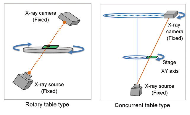
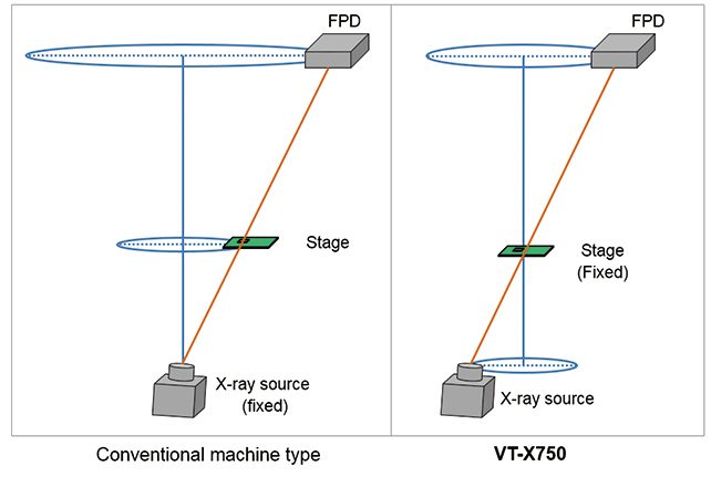
For the geometry design of our inline AXI system, a parallel table type is adopted instead of a rotary table type (Fig. 4). This is of a type intended to obtain CT images by changing the physical position of the X-ray source or X-ray camera (FPD) with respect to the object. This is because a rotary table type has a round, narrow field of view for 3D data imaging and hence tends to end up with images blurred at their edges with limitations on high-speed imaging due to the rotation speed limit1).
What is of particular importance about this parallel table type is the positioning accuracy of the XY-axis rotation trajectory. On the other hand, the Z-direction axis positioning accuracy also matters because this system is driven in the Z-axis direction when switching the inspection resolution or when tracing the bow of the workpiece under measurement by a displacement gauge.
A high-precision guide is provided for each axis, so that the positioning accuracy on the order of micrometers is achieved by our proprietary motor control technology. The XY-axis rotation accuracy in particular helps to obtain increasingly better CT images with the increase in roundness of the rotation trajectory. What serves as the foundation for this is high-quality mechanical parts mounted at the required degree of parallelism/straightness and the control technology based on our programmable logic controller (PLC) or servomotor that enables high-precision synchronous driving. In addition, the imaging devices are each supported with a high-rigidity frame and designed with a rugged hardware architecture to keep all terminal parts unaffected by vibrations.
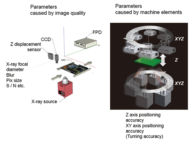
Thus, to obtain clear CT images, it is important not only to pursue the above-mentioned basic performance of the imaging devices or parameters associated with image quality but to develop a design that takes into consideration parameters associated with the mechanical components (Fig. 5). The parameters associated with mechanical components relate to the mechanical rigidity or weight balance of the system, the geometry design specifying how to turn the imaging devices, and the system architecture for realizing high-precision axis positioning control.
2.5 Robust correction processing and algorithm
Our AXI performs rapid processing and control of sensed information, not only in its hardware but also in its software application developed from our proprietary reconstruction process and algorithms and on our knowledge of visual inspection systems, to achieve a high degree of solder shape reproducibility and allow inspection of solder joint surfaces.
Assume, for example, that a workpiece is brought into the system for inspection; there will be variations in the stopping position. Therefore, our AXI system is equipped with a visible light source and a camera as well as with a technology that corrects variations or rotational shifts of the feed stop position on the workpiece conveyor using images obtained in visible light.
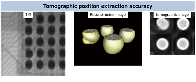
To perform algorithm processing accurately, it takes precision high enough to extract correct tomographic positions in a reconstructed image. Hence, the system is equipped with our displacement sensor and controller inside to measure the bow of the workpiece or the amount of deflection thereof and correct the Z-axis height position (Fig. 6).
3. Challenges towards inline full-surface inspection
Among the major challenges for the realization of inline fullsurface inspections are takt time improvements and system hardware reliability improvements. System hardware reliability relates to the weight and size of the enclosure, the dose to a workpiece under inspection, and maintainability. Each of the following sections describes one of these challenges.
3.1 Takt time problem
While capable of providing high-precision image quality, the CT imaging method is required to perform imaging during a 360-degree rotation and hence takes much takt time to do so. As a result, this method has a drawback of failing to meet the inline takt time.
In fact, our conventional model, the VT-X700, took approximately 70 seconds of inspection time apiece in a customerʼs circuit board inspection line. To put the VT-X700 into inline inspection use, this time should have been 37 seconds or less. Therefore, in many cases, the conventional VT-X700 model was introduced and used as an offline inspection system. For our AXI system to penetrate into inline use for SMT, the hardest challenge was how to achieve a short takt time.
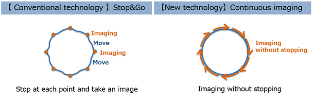
As the results of many engineering validation tests, it turned out that mechanical moving speeds and, especially, the XY-axis rotation speed needed a particularly significant improvement. The VT-X700 uses the so-called stop-and-go image acquisition method to obtain images with the axes held stopped during rotation on a 1PJ basis (1PJ=projection: a single, pre-reconstruction-phase image obtained at an angle during rotation). Hence, it needs much takt time per rotation. This stop-and-go image acquisition method is resistant to image blurring because image acquisition occurs only after the complete stop of the axes. The rotating hardware unit, however, experiences strong vibrations and impacts. Therefore, the X-ray source has to be a fixed type. Thus, we had no choice but to adopt a configuration in which the stage and the FPD rotate instead. This resulted in an FPD with a large rotation radius and hence in a mechanism that took much CT image acquisition time per rotation.
3.2 Enclosure size and weight issues
For actual inline use, consideration must also be given to the size and weight of the systemʼs enclosure. This is because the X-ray inspection system is relatively bulkier and heavier among the SMT equipment; therefore, transportability in a standardsize shipping container or the availability of a carry-in route and a sufficiently durable floor must be taken into consideration when considering delivery to and installation on the customerʼs production line. Therefore, if the weight and size of a unit increase as a result of the increased rigidity of mechanical parts, the system will become heavier and bulkier, leading to an increase in transportation and installation workloads and costs, which poses an obstacle to the introduction of the capital investment. These are key factors to be addressed when intending to introduce any system as inline equipment onto the production lines in the SMT market.
The VT-X700 Series only managed to support inspection of workpieces in sizes up to the so-called M size, which is 250 mm by 250 mm. Then, the third-generation model of the VT-X700-L was built to support inspection of large circuit boards up to 500 mm by 500 mm or more. This model, however, ended up with a system enclosure length of more than 2 meters and a system weight of more than 5 tons. Consequently, its installation onto a customerʼs line required special transportation equipment, forcing the customer to make a large capital investment. Moreover, if an attempt is made to expand the range of workpiece sizes supported for inspection while leaving unchanged the conventional geometry structure that allows the stage and the FPD to rotate with the radiation source fixed in position, the only result will be a huge stage and an even larger FPD rotation radius. This was why the takt time tended to be made even slower. As explained above, considering operability and installation requirements, the challenge was how to ensure the rigidity of the mechanism to prevent blurred images during continuous imaging while keeping the weight and size as low as possible.
3.3 Dose reduction issues for workpiece inspection
Speaking of the dose to a workpiece under inspection, an increase in the number of large circuit boards or parts to be inspected will lead to a longer irradiation time, thereby resulting in a higher dosage to the circuit board as a whole. In addition, there is also a tendency that more and more circuit boards are mounted with semiconductor devices and other parts vulnerable to radiation exposure. Accordingly, continuous efforts must be made to explore technologies for reducing the dosage on circuit boards.
3.4 Maintainability issues
The conventional model had problems with maintainability, such as both the inspection space and the device housing unit were in the same shielded space, and the individual devices were vertically arranged, poorly accessible by hand, invisible from a standing position, and did not easily allow tools in. Inline operation of a system in a customerʼs production line meant an increase in the availability rate of the system. In addition, because the system was between other pieces of equipment, the downtime for maintenance or the like had to be reduced to the very minimum. Moreover, the system had to be improved so that maintenance of all its components and parts could be performed from both the front and behind.
4. VT-X750 for realizing inline full-surface inspection
For many years, we have sought and explored technical solutions to the above challenges. Building upon a powerful continuous imaging technology for solving the takt time problem and a hardware design with improved reliability, we developed the VT-X750, a product with solutions to all the above-mentioned challenges.
4.1 Continuous imaging technology for solving the takt time problem
The following subsections describe the characteristics of the continuous imaging technology built into the VT-X750.
4.1.1 Means of implementation
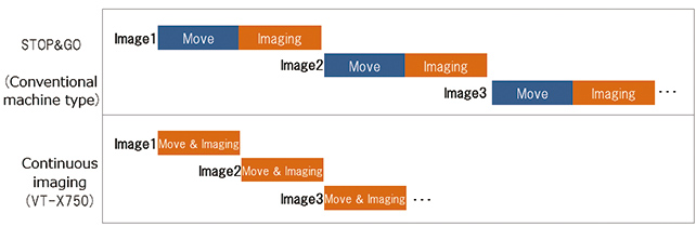
The first characteristic of note is that the mechanism keeps running without stopping during rotational imaging. To reduce the image acquisition time per field of view, we developed a technology that allows the mechanism to rotate without stopping and obtain one field of viewʼs worth of all images rather than repeat the cycle of moving, stopping, and image acquisition for each image as in the stop-and-go image acquisition method of the conventional model (Fig. 7).
The mechanism repeats rotary motion at a constant speed. Hence, the key is to synchronize the motions of the axes with each other to make the rotation trajectory as close to a perfect circle as possible. This is supported by a synchronous complete circular trajectory control technology based on our PLC NJ controller and the 1S servo system. This technology supports not only simple high-speed rotation of the axes but also dynamic and high-precision synchronous control of the axes.
The second characteristic of note is that this system performs image acquisition and data processing at high speed. This system is built in such a manner as to obtain one image after another, even in the middle of mechanical action, on the basis of image acquisition triggers issued by our proprietary circuit network. It is known that high-speed image acquisition during movement of the mechanism tend to result in blurred images2). Therefore, the system records the image acquisition start time on a 1PJ-by-1PJ basis and then reduces blur using its image reconstruction capability that takes into consideration the relative positions of the FPD and the X-ray source at that time. Moreover, with the addition of a graphics processing unit (GPU) for processing speed improvement, the system has successfully achieved a speed fast enough to process a series of images transmitted at high speed.
4.1.2 Results and effects
The result of such combination of high-precision motion control and high-speed sensing technology is continuous imaging technology. Released equipped with this continuous imaging technology in 2017, the VT-X750 is an innovative technological achievement that has enabled inline CT inspections at the required takt time. As compared with the conventional VT-X700 model, the rotational image acquisition time per field of view under the standard inspection conditions for double-side mounting circuit boards was successfully reduced by more than half from 7.7 seconds to 3.2 seconds. As a result, in the case of a circuit board manufactured by one of our customers in the automotive electronics industry, the inspection time apiece was reduced from approximately 70 seconds to 35 seconds, thus resulting in a two times faster inspection takt time (Fig. 8).
The advantage of this technology is that axis actions proceed at a constant speed and hence help to reduce vibrations and impacts on the rotating hardware units. This led us to adopt a geometry structure in which the X-ray source rotates with the stage unit, a heavy object, fixed in place. As a result, the rotation radius of the FPD and that of the X-ray source were reduced to approximately 60 percent of their respective corresponding conventional values, thereby contributing to a significant reduction in the speed required for a full rotation (Fig. 9). These reduced rotation radii also helped to reduce the above-mentioned image blur.
The factor at the heart of the architecture of the VT-X750 is seamless, synchronous control. This has been realized using our 1S servo driver and NJ controller. As far as these key devices are concerned, we adopt models equipped with an EtherCATbased general-purpose interface (IF) to allow design incorporation of their new functions into the system as soon as new versions are released.
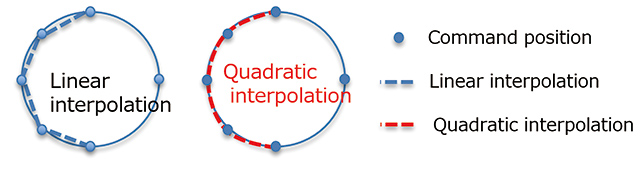
This allows immediate mounting of a more advanced servo driver whenever necessary. In 2019, the VT-X750 Ver. 2.0 will be released. For VT-X750 Ver. 2.0, developments have been made to further improve the axis accuracy in order to enable high-resolution inspections with a view to the microminiaturization of parts to be inspected in future. As the result of a joint research with our servo driver development department, the device has been upgraded to a servo driver equipped with a quadratic interpolation function (Fig. 10) suitable for multi-axis synchronous control. Then, the servo driver has been mounted into the system to further improve positioning accuracy.
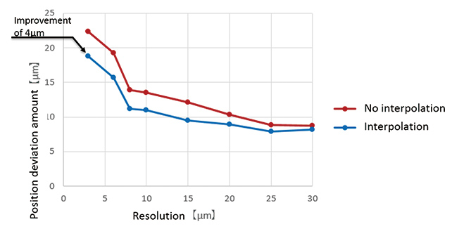
This function allows further improvements in the accuracy of the position deviation from the command value during synchronous control of the servo driver/NJ controller with each motor. The amount of position deviation of the completely circular trajectory during rotation was successfully improved by up to approximately 4 μm (Fig. 11).
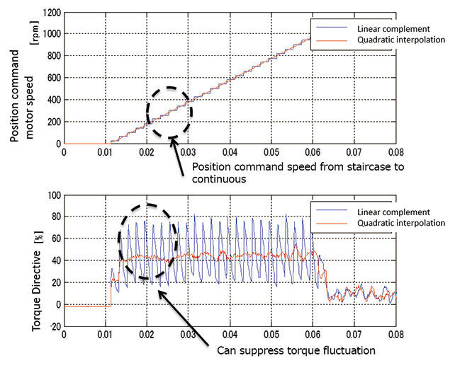
An improvement has been made to allow switching from the linear interpolation function to the quadratic interpolation function, so that the position command speed waveform will be switched from stepped to continuous. Thus, the deviation from the command value has been improved to allow reduction of torque variations, thereby making it possible to make the rotation trajectory closer to a perfect circle (Fig. 12).
With the axis accuracy improved in this way, the inspection resolution coverage ranging from 30 μm to 6 μm in VT-X750 Ver. 1.0 has been successfully expanded to that from 30 μm to 3 μm, including high-resolution bands, in VT-X750 Ver. 2.0. Advanced devices based on these correction technologies have been swiftly incorporated into the system to achieve precision enhancement without increasing hardware costs.
4.2 High-reliability hardware technology for actual inline use
4.2.1 Space-saving, high-rigidity technology for supporting high-precision, high-speed rotation
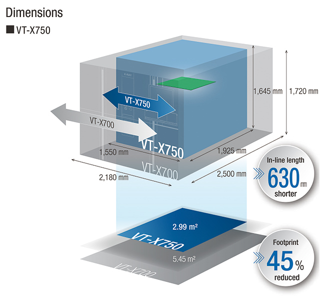
Equipped with continuous imaging and hence capable of rotation in a small space, the VT-X750 successfully features a hardware design that includes an inspection space and a control panel separated from each other. This allows compact optimization of the lead-shielded area, thus resulting in an improvement in terms of system size and weight. While housed in an enclosure sized almost the same as that of the M-size inspection version of the conventional VT-X700 model, the VT-X750 can inspect up to 500 mm x 500 mm workpieces equivalent to circuit boards inspected by the VT-X700-L. As a result, the VT-X750 has an installation footprint 45% smaller and a system weight 2 tons smaller than the VT-X700 while maintaining a sufficient rigidity of the mechanism not to cause image blur even at an axis rotation speed increased by continuous imaging (Fig. 13).
4.2.2 Filtering technology for realizing low-dose CT inspection
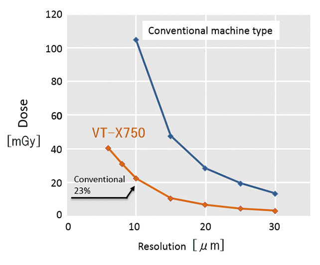
The VT-X750 is designed to deliver a lower dose per workpiece than the conventional model. First, with a significant improvement in the takt time, the X-ray dose to the workpiece has been reduced and significantly improved from that of the conventional model. Moreover, the beam emission window of the X-ray source is designed and equipped as standard with an Al filter capable of cutting low energy bands that affect analog element components, such as memory devices and semiconductors in the energy spectrum of the X-ray source. As a result, the dose per workpiece has been successfully reduced to 23 percent of that in the conventional VT-X700 Series (Fig. 14)3).
4.2.3 high-availability hardware architecture
The VT-X750 is built with the shielded inspection space and the control panel separated from each other. It is designed to allow access to all devices from the front for better maintainability. In particular, the control panel structure includes a door mechanism interlocked with a ground fault interrupter. Designed with safety in mind, the control panel door cannot be opened for maintenance without turning off the circuit breaker of the system first. Additionally, a general-purpose IF is used to reduce cables for easier cable maintenance. At the same time, considerations were given to loads on the human body to prevent work in difficult postures. All the above have been designed in line with the idea of ergonomics of the Semiconductor Equipment Materials International (SEMI) Standard4). Thus, equipment for inline operation, even if it breaks down, can now be maintained and repaired safely and quickly to minimize the downtime of the customerʼs production line.
5. Conclusion
Such a sophisticated architecture can maximize the advantage of continuous imaging technology. Moreover, the availability of faster inline CT inspections than before makes it possible to inspect far greater numbers of circuit boards than in conventional offline sampling inspections, thereby enabling contribution to improved product quality in a wider range of customersʼ circuit board production lines in preparation for the automated driving society to come.
This paper outlined a continuous imaging technology for both delivering both high speed and CT detection capabilities at the same time and the VT-X750 with its innovative hardware structure. While the main focus of the description was placed this time on hardware-related areas, the automated inspection algorithm is also built with inclusion of our many proprietary technologies. Featuring excellent shape reproducibility and optimized on the advantages of CT, this inspection algorithm can handle processes at a takt time required for inline inspections without lagging behind high-speed imaging systems.
As for future prospects, we will design an efficient inspection process coordinated with visual inspection systems and promote development of operational assistance with reduced programming person-hours, while improving the inspection algorithm for more precise reproduction and quantitative measurement of soldered joint shapes. Exploration into technologies for further improving AXIʼs takt time will lead to the realization of in-line full surface inspection inspection of circuit boards mounted with devices whose solder joints are all on their underside5). Therefore, we will encourage further penetration of Omronʼs AXI into the SMT market including the automotive industry to contribute to improving customer product quality.
References
- 1)
- Sugita, S. High-speed CT inspection technology for wider coverage of mounting quality assurance (in Japanese). Proceedings of the 52nd Soldering Breakout Session, Japan Welding Society, 2011, p.4.
- 2)
- Japanese Society of Radiological Technology (Supervising Ed.). Ichikawa, K.; Muramatsu, Y. eds., Standard X-Ray CT Image Measurement (in Japanese). Ohmsha, 2009, pp.27-28.
- 3)
- Onishi, T. Inline automated X-ray inspection system with high-speed, high-resolution, low-dose inspection capability (in Japanese). Image Laboratory. 2018, Vol.29, No.1, pp.67-72.
- 4)
- SEMI S8-1116. Safety Guidelines for Ergonomic Engineering of Semiconductor Manufacturing Equipment. SEMI International Standards, 2016.
- 5)
- Jisso Technology Roadmap Committee. Jisso Technology Roadmap 2015 (in Japanese). Japan Electronics and Information Technology Industries Association, 2015, pp.354-355.
The names of products in the text may be trademarks of each company.