


Development of the Device Body Shape and Contact Detection Function to Realize High-quality Waveform Recording Effective for Diagnosis with the Portable Electrocardiograph for Home Use
- Electrocardiograph
- Portable
- Home
- Chassis
- Contact Resistance
Traditionally, electrocardiograms (ECG) have mainly employed the use of 12-lead ECG or Holter monitors in the medical field. However, depending on the patient, symptoms do not always appear on the waveform, and there are some patients whose symptoms cannot be detected by recording for a few seconds to a few days as with conventional ECGs. Portable ECGs that can record at home when symptoms appear are becoming increasingly important for patients and doctors who were previously unable to detect symptoms. But the current portable ECG size is too large to be carried in a pocket. More miniaturization of portable ECG is required. For its realization, it is effective to eliminate the display that previously showed waveforms on the device; however, this is expected to result in a deterioration in waveform quality because the waveform display during recording, which was effective in stabilizing the recording posture, will be eliminated, and it will be difficult to maintain a stable recording posture as the device itself becomes smaller. This paper describes the results of our study on the no display ECG’s body shape for recording high-quality waveforms and the contact detection function for stable contact resistance.
1. Introduction
1.1 Background
The mainstream method of obtaining diagnostic electrocardiograms (ECGs) has been the use of 12-lead electrocardiograph (ECG) machines and Holter monitors, both of which have been widely used in medical settings for a long time1).
- 12-lead ECG machines: Used to record 12 different lead waveforms from 10 electrodes fitted on the four limbs and chest. The recording time per session is short and takes approximately 10 seconds. Used to record the ECG of patients lying at rest in the supine position in the hospital.
- Holter monitors: Equipped with leads, these ECG devices basically record two or three different lead waveforms. Primarily used to record 24- to 48-hour-long ECGs. Pasting of the electrodes onto the skin is performed at medical institutions.
However, symptoms do not always manifest on the ECG, depending on the patient. Many cases exist of patients who go to the doctor for diagnosis out of anxiety. However, they often fall short of being definitively diagnosed. Demand is growing for at-home ECG recording because of the existence of such patients whose symptoms go undetected with conventional hospital-centered ECG recording. In response, a wider variety of home ECG recording devices have become available, as listed below, usefully serving the needs of both patients and doctors who have been otherwise unable to detect symptoms1).
- Paste-on ECG devices: Compact, lightweight, and used with the electrodes pasted directly on the chest. Intended for continuous recording for a long duration exceeding 24 hours. Single ECG lead, no lead wire, waterproof, and less physically constraining.
- Portable ECG devices: Mainly intended to record one or up to six different lead waveforms. Easy to carry. Pressed against the palm or chest by the patient as necessary to record the ECG. The recording time per session is approximately 30 seconds. No need for constant electrode-skin contact. Less stressful for the patient, except during recording sessions.
- Wearable ECG devices: These devices have become increasingly common in recent years. The mainstream is smartwatch types. Worn mainly to record single-lead waveforms. The recording time per session is approximately 30 seconds. Worn all the time. Hence, useful for patients without subjective symptoms or those with infrequent symptoms.
- Implantable ECG devices: Implanted beneath the skin in the chest for continuous ECG monitoring of single-lead waveforms. Used to detect diseased conditions, which are hard to detect even with long hours of ECG.
The demand for further reducing the size of portable and wearable ECG devices is expected to intensify in the future, considering the effectiveness of their portability in daily life in alleviating the patient burden.
1.2 Challenge
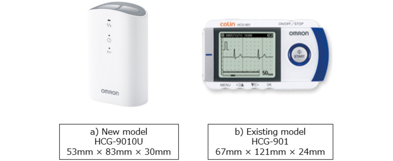
As mentioned above, smaller portable ECG devices are in demand for the early treatment of patients through at-home ECG recording. So far, the HCG-801 and the HCG-901 (both manufactured by OMRON Healthcare Co., Ltd., Kyoto Prefecture, Japan), the portable ECG devices shown in Fig. 1, have been widely used by medical practitioners for at-home ECG recording applications. On the one hand, these models are equipped with a display to show waveforms, enabling stable waveform recording. On the other hand, the display poses a constraint on device miniaturization. Enabling stable ECG waveform recording without a display would lead to further smaller devices with higher portability.

However, portable and wearable ECG devices are more prone to degraded waveform quality than 12-lead ECG machines for recording during rest in the hospital or on Holter monitors with patch electrodes pasted on the skin by the doctor. The cause is that because the patient must press the electrodes onto the skin for recording, the resulting patient’s body motion and physical straining can easily cause the noise mentioned below to occur in the waveform. Hence, further reducing the size of portable ECG devices, which already pose difficulties maintaining a stable recording posture, will make the device even harder to hold in place, potentially resulting in a more unstable recording posture that may even further degrade waveform quality.
This paper presents an exploration of the balance between the miniaturization of portable ECG devices and the retention of waveform quality.
2. ECG waveform quality
Section 2 examines the causes responsible for ECG waveform quality degradation as identified in Section 1 as a challenge and considers the corresponding solutions.
2.1 Causes of noise
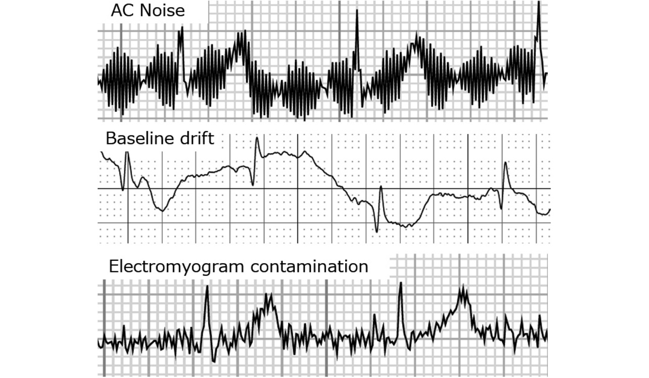
The causes of ECG waveform noise are primarily the three given below. Fig. 2 shows specific examples of noisy waveforms.
- 1) Alternating-current interference (hum)
- A regular, small-amplitude noise with a constant wave height and width. Caused by electromagnetic radiation from electrical equipment. Our objective of device miniaturization does not influence hum. Hence, hum is excluded from the discussion below.
- 2) Baseline drift
- Caused by the change in electrode-skin impedance. Baseline drift occurs when the electrode and skin move from the patient’s body motion, large breath, or conversation. The patient’s strain, physical strength, range of motion of each joint, and skin dryness condition also have an influence.
- 3) Electromyogram (EMG) contamination
- Caused by the patient’s strain- or anxiety-induced involuntary movements, such as stiffening and shivering, or by cold-induced shaking. Often observed in patients with lordosis, kyphosis, or scoliosis, as well as in those with diseases involving shaking of the limbs or those with the limbs constrained by clothing.
Unlike 12-lead ECG machines or Holter monitors, portable ECG devices are operated by the patients themselves. As such, these devices are prone to baseline drift in Item 2 and EMG contamination in Item 3. When the patient presses the device against the skin in a standing or seated posture, the arm can easily be strained just by holding the device in place, resulting in EMG noise. Moreover, the device’s condition of being pressed against the skin is also easily changeable by posture changes and breathing during recording sessions. These body motions manifest as baseline drift. Unlike 12-lead ECG machines and Holter monitors, portable ECG devices are used without electrodes pasted on the skin. The resulting high contact resistance also poses a destabilizing factor.
The causes of the above-mentioned noise occurrences are diverse, including the patient’s hand size, muscle strength, age, and use environment. Additionally, we removed the display from the device to facilitate miniaturization. The resulting inability of the patient to view the waveform during recording posed the risk that a degraded waveform might go
unnoticed.
2.2 Noise reduction
For portable ECG devices, and particularly for a device that records the single lead waveform in the chest lead (device held and pressed against the chest by the right hand), we implemented the following two measures to reduce noise and obtain high-quality waveforms:
- (1) Achieve a device shape that is easy for anyone to hold without straining the body excessively or without losing a stable posture.
- (2) Achieve a function to check first for electrode-skin contact stability and start recording only after confirming stable contact.
Measures (1) and (2) are discussed in detail in Sections 3 and 4 below, “Enclosure shape-based study of noise reduction” and “Contact detection-based study of noise reduction,” respectively. From the perspective of mass-producibility (cost and parts/materials availability), the electrode material and area remained unchanged throughout the investigation herein. Additionally, our premise was that the proposed device was intended to record single-lead waveforms. Hence, our investigation used a total of three electrodes: two for waveform recording and one for grounding.
3. Enclosure shape-based study of noise reduction
3.1 Guidelines for shape consideration
This subsection describes the shapes under study and bases itself on the results of prototyping to give a summary of important points for waveform stabilization. Our objective was to prevent baseline drift and EMG contamination, the causes of noise 2 and 3 mentioned in Subsection 2.1, by ensuring that the held device not wobble and that the held arm or trunk remain relaxed. Therefore, we considered the following four points as the factors beneficial to waveform stabilization:
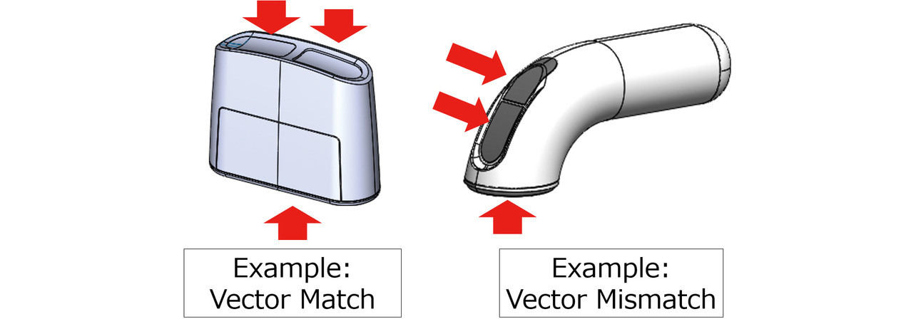
- Factor 1: The directions in which the electrodes are pressed against the skin are on the same vector. Otherwise, the patient must apply force in different directions with the fingers and arm differently oriented. Depending on the subject’s conditions (e.g., finger-applied forces, hand size, finger lengths, and the range of motion of each joint), a vector mismatch may result in uneven force applied to each electrode or straining of the body. Fig. 3 shows an example of such cases.
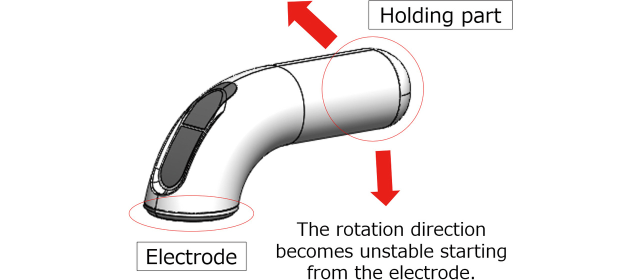
- Factor 2: The main-body grip part is disposed close to the electrode part. Otherwise, the patient in the device-holding posture during recording will likely let the force in the turning direction act on the device. The resulting loss of stability may cause the device to wobble, depending on the subject. Fig. 4 shows an example of such cases.
- Factor 3: The device-holding posture aligns with the parameters of the human body structure, such as the natural orientations, curves, and ranges of motion of joints. For example, when a patient with stiff finger joints or reduced arm or trunk muscle strength holds the device in an unnatural posture, the electrodes may make inaccurate contact with the skin, or unnecessary force may occur because of the unnatural posture, resulting in EMG contamination.
- Factor 4: The electrode contact part is shaped to make uniform contact with the skin for all users, regardless of sex or body shape. Body shape differences tend to be more pronounced in the chest and abdomen. For example, in the case of female patients, the available electrode-skin contact area is limited because placing the device on the breasts must be avoided. Additionally, a low-height enclosure would reduce visual accessibility to the contact site. Obese people with layers of superfluous flesh or skinny and bony people have trouble finding a flat electrode-skin contact surface on their bodies.
3.2 Shape samples
Considering the structure of the human body, we considered and prototyped the following Sample Nos. 1 to 5 as shapes that allow the user to grip the device and press its electrodes against the skin in a natural posture. Fig. 5 shows the specific appearances of these shapes:
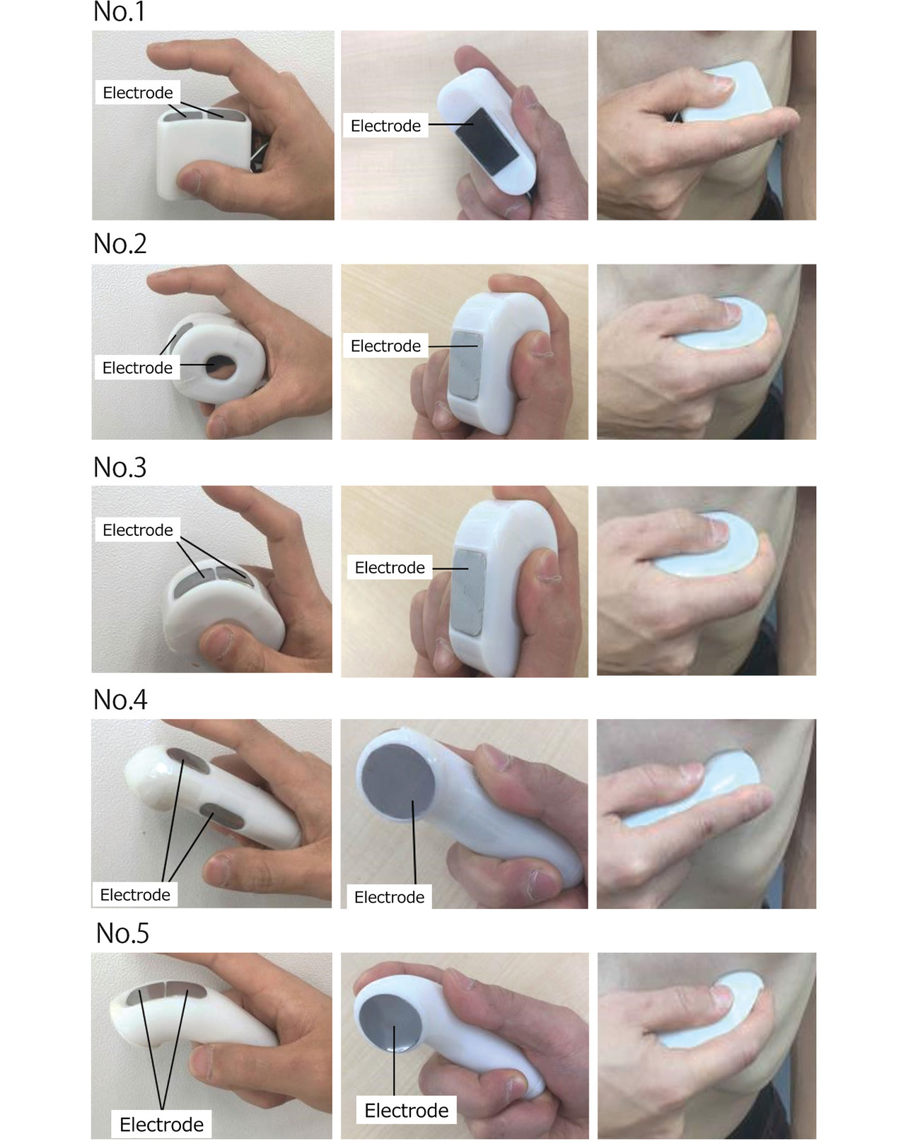
No. 1: A sample based on an existing product, HCG-801. Obtained by reducing the overall size of HCG-801.
Nos. 2 and 3: Samples designed to allow the user to angle the wrist and curl the finger into a more ergonomically natural curve.
Nos. 4 and 5: Samples designed to allow the user to press the electrode on a desired target point with a clear aim at it.
The paired samples, Sample Nos. 2 and 3, were enclosures intended for the same holding posture. So were the other pair, Sample Nos. 4 and 5. Sample Nos. 3 and 5 had the ground electrode and one of the recording electrodes disposed side by side. Sample Nos. 2 and 4 had the three electrodes disposed apart from one another.
Table 1 summarizes the relationship between the samples and the factors under study. Each ✓ indicates that the sample satisfied the applicable factor, and each × means that the sample failed to satisfy the applicable factor.
| Sample | Factor 1 | Factor 2 | Factor 3 | Factor 4 |
|---|---|---|---|---|
| No. 1 | ✓ | ✓ | ✓ | ✓ |
| No. 2 | × | ✓ | ✓ | ✓ |
| No. 3 | × | ✓ | ✓ | ✓ |
| No. 4 | × | × | × | ✓ |
| No. 5 | × | × | × | ✓ |
3.3 Evaluation method
We evaluated each sample for waveform quality against the following criteria:
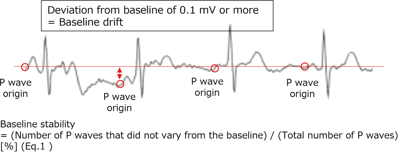
(1) Baseline drift: We checked waveforms for the width of deviation from the baseline to each P wave onset point. Waves showing a variation of 0.1 mV or more from the baseline were determined as drift waves. The criterion of 0.1 mV was empirically determined to be appropriate for assessing the acceptability of devices and was adopted accordingly. The 30-second variability from the baseline was converted into numbers using Eq. 1 (see Fig. 6). The waveform containing the least variation with a near-100% baseline stability was determined as a stable waveform insignificantly affected by body motions.
(2) EMG contamination: We visually inspected waveforms for noise at levels that could potentially affect the P wave reading. Waveforms too noisy for accurate P wave reading were found to be of insufficient quality for diagnostic use. Fig. 7 shows a typical waveform containing hard-to-read P waves. The visual inspection was performed by multiple development staff members.

The subjects were as described below. Prior to the evaluation study, we received authorization from the in-house Ethics Review Committee and obtained sufficient informed consent from the subjects.
- Number of subjects: 10 persons (5 males and 5 females)
- Age bracket: 68 to 81 years old
- Study period: Feb. 25, 2019, to Mar. 4, 2019
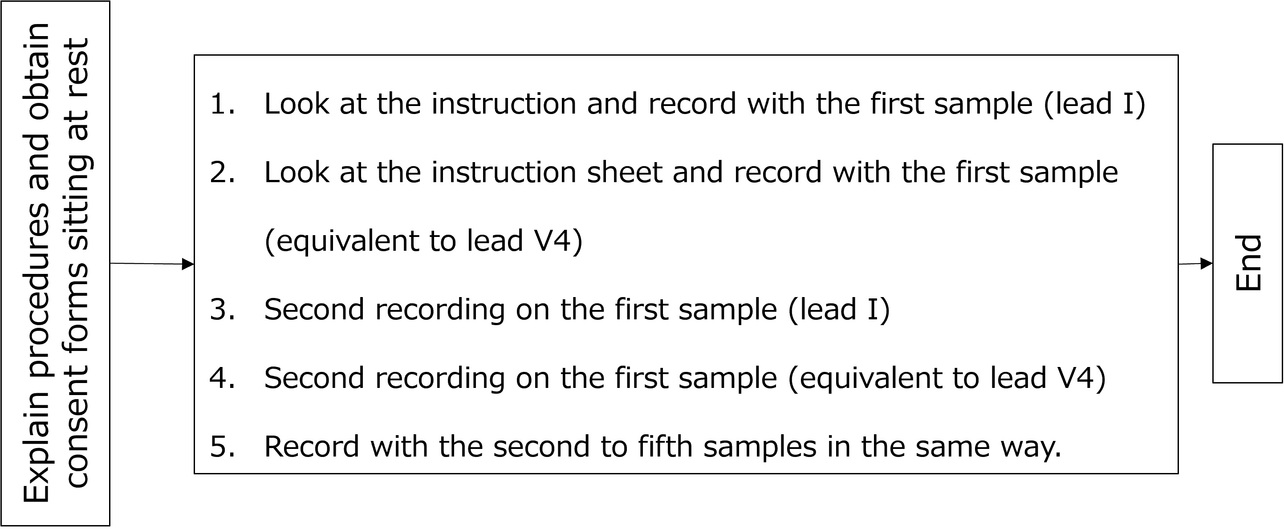
- Evaluation method: The circuit used was that of the existing product. Only the enclosure was replaced. Then, as shown in Fig. 8, each subject was asked to take two ECG records per sample, each 30 seconds long. The evaluation order of the samples was shuffled for each subject using a random number table. Two recording postures were used: one, Lead I (right hand-to-left hand), and the other, V4 equivalent (right hand-to-chest).
The evaluations in Section 3, “Enclosure shape-based study of noise reduction,” and Section 4, “Contact detection-based study of noise reduction,” were intended to estimate the order of superiority among the shapes. Each study involved approximately 10 subjects. Ultimately, we confirmed the effectiveness of the device based on the product’s waveform quality study in Section 5.
3.4 Evaluation results
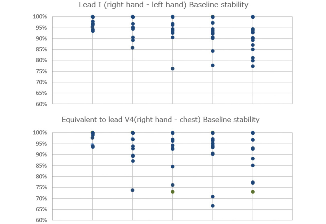
Fig. 9 and Table 2 show the evaluation results for baseline drift. The samples tended to be in the following order, based on relative superiority in baseline stability: No. 1 > Nos. 2 and 3 > Nos. 4 and 5. Satisfying all four factors, Sample No. 1 performed best in baseline stability. Its shape excelled in stability with low variation between subjects. Sample Nos. 2 and 3 also demonstrated good baseline stability. However, they showed considerable variations by subject, especially during recording on a V4 equivalent lead. Sample Nos. 4 and 5 showed significant variations by subject in whichever recording posture and turned out to be unsuitably shaped for use by a large population of patients.
| Sample | Factor 1 | Factor 2 | Factor 3 | Factor 4 | Baseline stability |
|---|---|---|---|---|---|
| No. 1 | ✓ | ✓ | ✓ | ✓ | A |
| No. 2 | × | ✓ | ✓ | ✓ | B |
| No. 3 | × | ✓ | ✓ | ✓ | B |
| No. 4 | × | × | × | ✓ | B |
| No. 5 | × | × | × | ✓ | C |
The acceptable amount of baseline drift varies depending on the doctor’s proficiency or the purpose and cannot be determined by generalization. However, a more stable waveform would broaden the range of qualified doctors or that of acceptable purposes. Therefore, Sample No. 1, which showed stable results with low variations between subjects, was determined to be most suitably shaped for portable ECG devices.
From the above, we confirmed that satisfying all the four factors assumed in advance, as shown in Table 2, is crucial in improving waveform quality.
- Factor 1: The directions in which the electrodes are pressed against the skin are on the same vector.
- Factor 2: The main-body grip part is detached from the electrode part, showing no instability in the turning direction.
- Factor 3: The device-holding posture aligns with the parameters of the human body structure, such as the natural orientations, curves, and ranges of motion of joints.
- Factor 4: The electrode contact part is shaped to make uniform contact with the skin for all users, regardless of sex or body shape.
The evaluation results showed no significant differences in EMG noise by shape. Hence, we only referred to the results for baseline drift this time.
4. Contact detection-based study of noise reduction
4.1 Concept of contact detection
When the skin-electrode contact force is weak or when the skin is dry, body motion can easily affect the skin-electrode contact resistance, resulting in an increased likelihood of an ECG waveform containing baseline drift noise. Therefore, our design is devised to start automatic recording only after verifying the retention of a stable contact condition. This design prevents recording without proper electrode contact, thereby ensuring the acquisition of high-quality waveforms.
Fig. 10 shows a block diagram of the contact detection circuit. During contact detection, the pull-up resistors connect the ECG input electrodes (finger and chest electrodes) to their respective corresponding power supply potentials. More specifically, when each electrode comes into contact with the skin, its potential arises as a result of the power supply potential being divided between the pull-up resistor and the human body resistor. With stable electrode-skin contact and sufficiently low contact resistance, the electrode potential decreases accordingly.
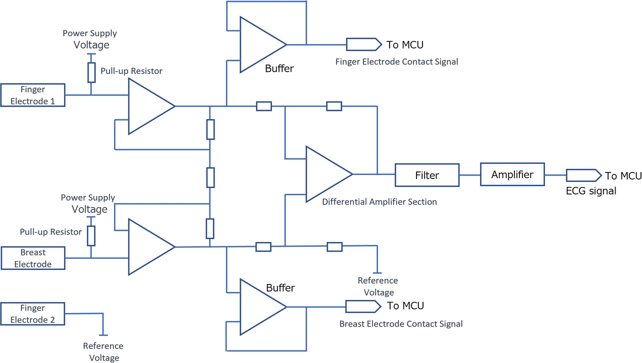
When confirming that the electrode potential has dropped to the judgment-reference voltage, this function determines that the contact has stabilized and starts ECG recording.
4.2 Method of determining contact detection criteria
This method flows as follows:
For each subject, an ECG device equipped with the contact detection circuit described in Subsection 4.1 is used to record the ECG waveform. At the same time, the contact resistance value is measured (calculated from the electrode potential). The score point obtained by converting the recording quality of the ECG waveform is compared with the contact resistance value to derive the criteria for contact resistance sufficient to record acceptable ECG waveforms.
We conducted an evaluation study for the subject group detailed below. Prior to the evaluation study, we received authorization from the in-house Ethics Review Committee and obtained sufficient informed consent from the subjects.
- Number of subjects: Eight persons
- Study period: Mar. 1, 2023, to Mar. 25, 2023
- Evaluation method: Each subject was handed the ECG device and asked to record ECG at home. They were required to take a total of four records per day, one on awakening, another before sleep, and two more at rest, for three consecutive days.
4.3 Evaluation results
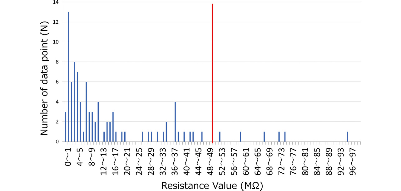
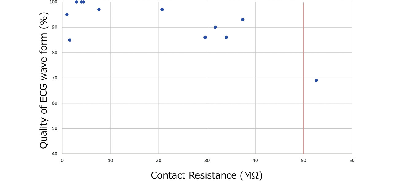
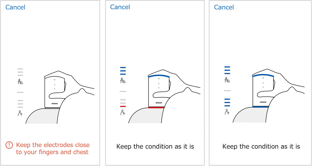
Based on the evaluation results, we examined the relationship between the contact resistance value and waveform quality. Fig. 11 shows the distribution of finger and chest contact resistances for all the subjects. Some subjects took more records than the required four, resulting in a total record count of 93 data points. Meanwhile, Fig. 12 shows the relationship between contact resistance and waveform quality. For Fig. 12, we used data from four subjects, those with particularly low-quality waveforms among all subjects. The same procedure as the evaluation method in Subsection 3.3 was used for waveform quality conversion into scores, which indicate the proportion of the stable baseline duration to the 30-second ECG record waveform. From the perspective of ECG reading, we set the reference value as follows on the basis of the empirical value established at the development department: At least 80% of the recorded ECG waveform duration should be accounted for by the stable baseline portion. Considering that the finger and chest contact resistances showed no significant difference in the degree of impact on the waveform quality, we summarized the results without distinction between finger and chest data. While the contact resistance value data points concentrate at or below 20 MΩ, their distribution spans the range from above 20 MΩ to 100 MΩ. Additionally, ECG records taken at or above 50 MΩ exhibit results with degraded waveform quality. A high contact resistance can easily cause attenuation of ECG waveforms. As a result, the ECG baseline becomes easily changeable under the influence of body motions. Hence, when a reference value set for contact resistance is exceeded, a possible solution is to urge the user to increase the skin-electrode contact force or to moisten the skin with water to improve the recording quality. For our newly developed models HCG-8010T12) and HCG-9010U3), the reference resistance is a contact resistance of 50 MΩ. When the reference contact resistance is exceeded, these two models delay the start of ECG recording (with some exceptions) for better ECG waveform quality. Moreover, the HCG-8010T, designed for plugged-in use with a dedicated app, provides the user via the app with feedback on a poor contact condition as shown in Fig. 13. This app uses colors and a three-level bar indicator to inform the user of the electrode-skin contact condition and guide them to a more desirable contact condition.
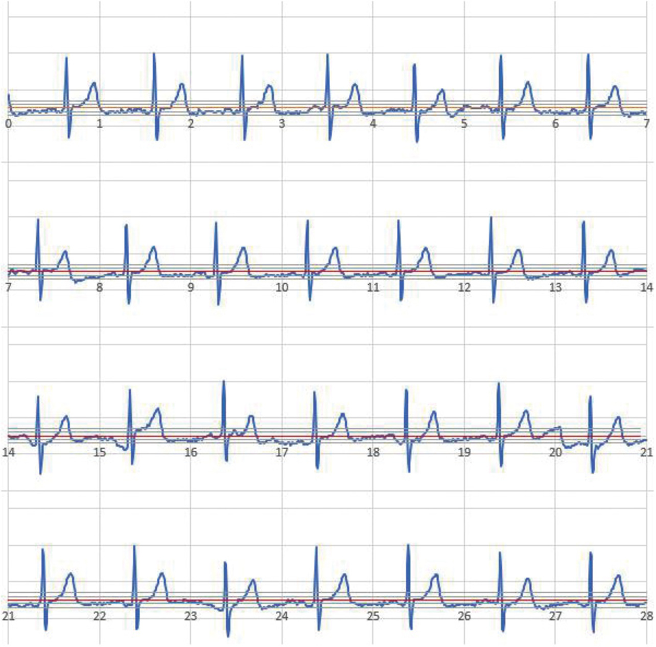
For reference, Fig. 14 shows a typical case of ECG recording with high contact resistance. This ECG is an example of recording with a contact resistance of 50 MΩ or more. In this example, baseline drift is visible, making the recorded results a hard-to-read ECG. Our contact detection function prevents the recording of such noisy waveforms, thereby enabling the acquisition of diagnostically useful waveforms.
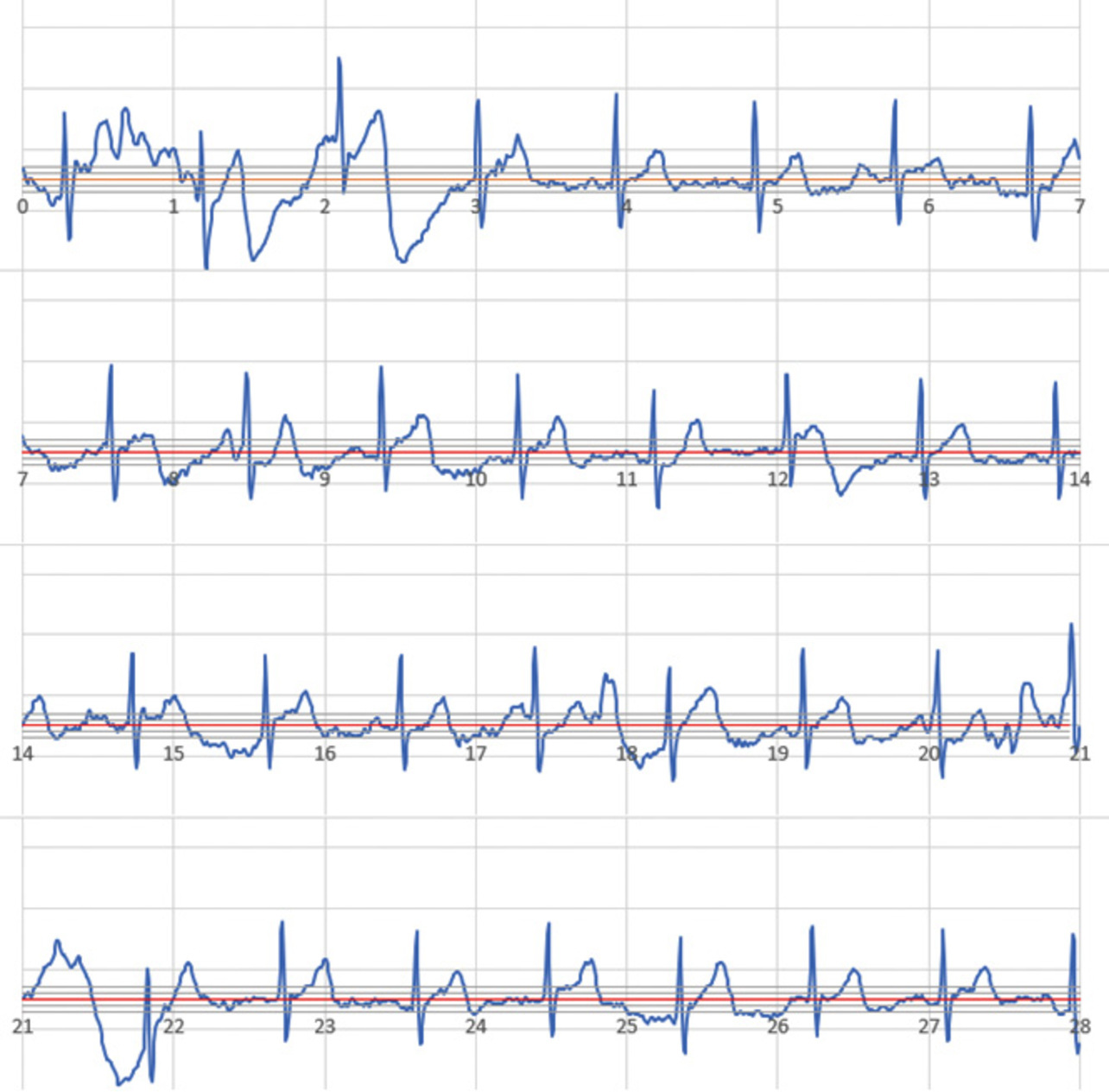
A high contact resistance does not necessarily cause baseline drift. However, the evaluation results indicate that it leads to a condition in which the ECG waveform quality can easily degrade under the influence of body motion during recording.
Fig. 15 shows a typical ECG waveform record with low contact resistance in the same subject. The contact resistance from this recording session was low at 9.7 MΩ, indicating that the ECG waveform was recorded along the baseline.
5. Product’s waveform quality
Using a physical prototype of the HCG-9010U, which reflects the study content of this paper, we performed a verification of waveform quality. This prototype was shaped similarly to the existing model. However, with the display removed, as shown in Fig. 16a. To verify the practical feasibility of the prototype, we recorded ECG waveforms of patients with the target symptoms for our ECG waveform recording products. Prior to the evaluation study, we received authorization from the Ethics Review Committee of the study’s host hospital and obtained sufficient informed consent from the subjects.
5.1 Content of the verification
- Location: Koseikai Clinic (Kyoto City, Kyoto, Japan)
- Number of subjects: 27 persons
The breakdown of symptoms diagnosed by the doctor based on the verification results is as follows:
- - Normal: Eight persons
- - Tachycardia/bradycardia: Three persons
- - Atrial fibrillation: Five persons
- - Extrasystole/supraventricular extrasystole: Five persons
- - ST Up / ST Down / Negative T-wave: Four persons
- - Other (AV block, T-wave flat-low): Two persons
- Study period: Jun. 17, 2023, to Jul. 26, 2023
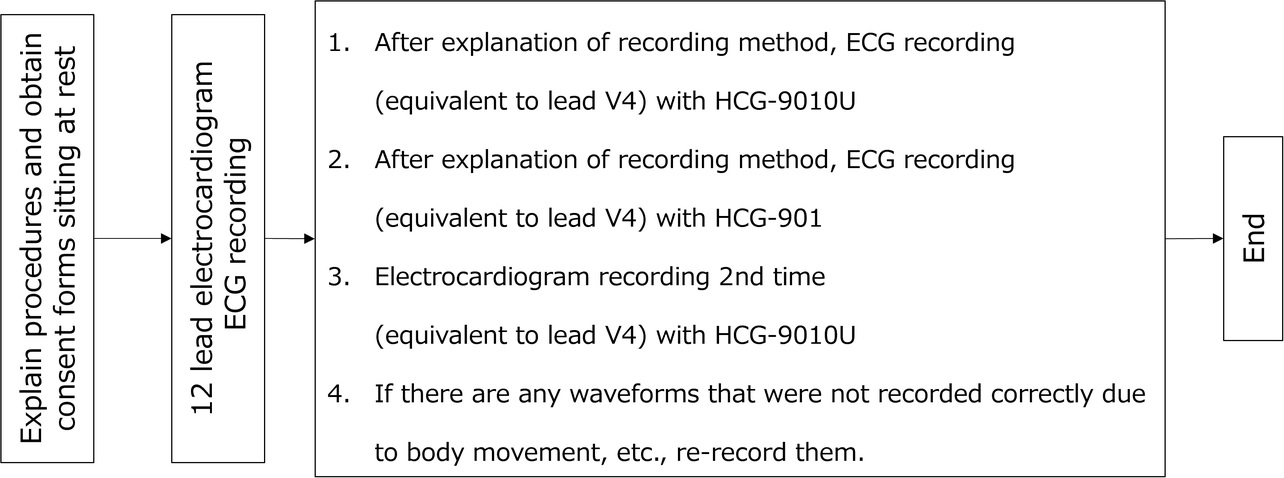
- Recording procedure: After recording ECG with a 12-lead ECG machine as in Fig. 17, record ECG with the HCG-9010U, in which the function presented herein is incorporated, and the HCG-901, the existing ECG device.
- Recording postures: Supine position for recording with the 12-lead ECG machine. Seated position and the postures actually taken for recording with the portable ECG device.
- Result judgment: Based on the waveforms recorded with the 12-lead ECG machine and the portable ECG device, the doctor examined whether the new model exhibited diagnostically impactful waveform quality degradation. For any difference in symptom detection between the waveforms recorded with the 12-lead ECG machine and the portable ECG device, a comparison was made with the existing ECG device to ensure the equivalence of the results to those conventionally achievable.
5.2 Verification results
The results of a comparison made by the doctor of the 12-lead ECG machine and the portable ECG device waveforms showed that in 26 cases out of 27, the diagnostic results for both waveforms agreed with each other, confirming that the portable ECG device could correctly read symptoms. In the remaining case with disagreeing results, the 12-lead ECG machine exhibited a T-wave flat-low while the portable ECG device showed a normal waveform. This difference occurred because the 12-lead ECG machine read a T-wave flat-low in the V6 lead, whereas the portable ECG device had only a V4 equivalent lead, showing no diseased condition in the waveform. The existing device also showed similar results. The cause was the influence of the difference in the target lead but not that of the device’s waveform quality. Thus, the portable ECG device was confirmed to have recorded waveforms of sufficient quality for a correct diagnosis. Additionally, the doctor’s comment confirmed the absence of poor-quality waveforms, which could have led to misdiagnoses.
6. Conclusions
The study results confirmed that satisfying the following four factors is crucial in stabilizing the quality of waveforms:
- The directions in which the electrodes are pressed against the skin are on the same vector.
- The main-body grip part is detached from the electrode part, showing no instability in the turning direction
- The device-holding posture aligns with the parameters of the human body structure, such as the natural orientations, curves, and ranges of motion of joints.
- The electrode contact part is shaped to make uniform contact with the skin for all users, regardless of sex or body shape.
Additionally, we clarified the necessary contact resistance for stable waveform recording and successfully considered a function that automatically initiates recording only after verifying its retention. These measures enabled high-quality ECG waveform recording, even with a display-less portable ECG device unable to check the waveform quality during recording, thereby achieving miniaturization for improved portability.
We completed the main-body shape presented in Section 3 with the cooperation of Mr. Brian Brigham and Mr. Kosuke Inoue, who were members of the Design Department, Product Operations Management Division, OMRON Healthcare Co., Ltd., at the time of the research. We thank those two for their contributions.
During the evaluation study presented in Section 5, we also received extensive cooperation from Dr. Izuru Masuda and other staff at the Koseikai Clinic, including the EGC technicians and nurses. We are thankful to them for their cooperation.
References
- 1)
- T. Ikeda et al., “2024 Japanese Heart Rhythm Society/Japanese Circulation Society Consensus Statement on the Appropriate Use of Ambulatory and Wearable Electrocardiographs,” (in Japanese), ECG, vol. 44, no. 4, pp. 275-307, 2024.
- 2)
- OMRON HEALTHCARE Co., Ltd. “Portable ECG Device HCG-8010T1.” (in Japanese), OMRON Healthcare Store. https://store.healthcare.omron.co.jp/category/28/HCG_8010T1.html (Accessed: Jan. 15, 2025).
- 3)
- OMRON HEALTHCARE Co., Ltd. “Portable ECG Device HCG-9010U.” (in Japanese), OMRON Healthcare Store. https://store.healthcare.omron.co.jp/item/HCG_9010U.html (Accessed: Jan. 15, 2025).
The names of products in the text may be trademarks of each company.