


Development of a Millimeter-Wave Radar Hood with Quantitative Snow Avoidance and Vehicle Detection Accuracy
- Millimeter-wave radar
- Millimeter-wave radar food
- ITS (Intelligent Transport Systems)
- Snow accretion test
- Vehicle detection
It is crucial to utilize an intelligent transport system that gathers vehicle information from sensors installed as part of the road traffic infrastructure and uses this data for signal control and support for autonomous driving to ensure safe and smooth traffic flow control. We have developed millimeter-wave radars for future traffic monitoring. Millimeter-wave radars can gather vehicle information over a wider range compared to other sensors. However, when snow accumulates on the radar’s emission surface, it causes the radio waves to attenuate, leading to a decrease in detection accuracy. Therefore, we developed a snow protection hood because we would like to try spreading millimeter-wave radars throughout Japan, including snowy regions. In this report, we quantified the target amount of snow and wind for the design of the snow protection hood. Furthermore, we determined a hood shape that would not affect vehicle detection accuracy by attaching the hood to the sensor as confirmed through an electromagnetic field simulation. In conclusion, we would like to report those results that we have experimentally confirmed the effectiveness in terms of both snow avoidance and vehicle detection.
1. Introduction
The Japanese government lays out its Traffic Safety Basic Plan approximately every five years, aiming to achieve the world’s safest road traffic environment. Measures are currently promoted under the 11th Traffic Safety Basic Plan for the five years from the FY 2021 to 20251). Specific examples given of these measures include the effective use of Intelligent Transport Systems (hereinafter “ITSs”). As regards the intended purpose of the effective use of ITSs, consideration is underway to facilitate smoother traffic flows through such methods as traffic jam reduction while improving the safety, transportation efficiency, and comfort of road traffic. One of the measures pursued in this direction is promoting infrastructure development so that traffic detectors can collect and provide detailed information on road traffic. A plan is underway to aggregate and distribute a wide range of road traffic information, such as real-time vehicle travel history (probe) information, to complement the information available from the infrastructure.
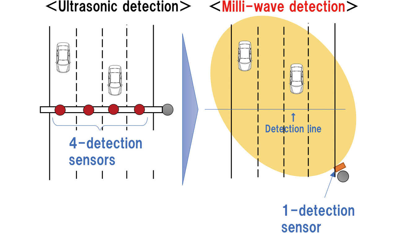
Based on this measure, we are deploying millimeter-wave radars capable of collecting a broader range of vehicle information at lower costs as an alternative to ultrasonic wave sensors used to collect traffic volume data from existing non-toll roads. Traffic detector types are specified by the National Police Agency2). The traffic detectors currently in the most widespread use in Japan are ultrasonic wave sensors3). Millimeter-wave radars have several advantages over these ultrasonic wave sensors. As shown in Fig. 1, a radar of this type can detect vehicles in multiple lanes on its own and is installable on a road shoulder and features excellent maintainability. Moreover, unlike ultrasonic wave sensors, this radar uses not a specific point but a unit coverage area for vehicle detection and, as such, can obtain various data, including vehicle behavior4). In other words, while an ultrasonic wave sensor estimates the behavior of vehicles as they pass its installation point, millimeter-wave radar can grasp the behavior of vehicles at points other than where it is installed. As such, the latter can detect the start of vehicles waiting at traffic lights and the lengths of vehicle queues, among other things. This advantage will be exploited to coordinate millimeter-wave radars and signal controllers for appropriate signal control, giving rise to expectations for effective applications to ITSs5), such as traffic jam alleviation.
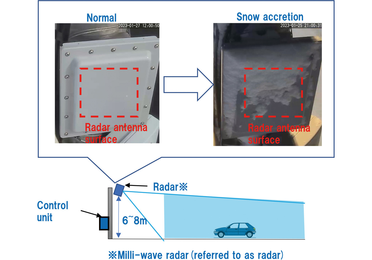
As shown in Fig. 2, millimeter-wave radar is installed at a height to emit a radio wave downward at the road surface. Installed this way, the radar can measure vehicles traveling over a wide range. On the other hand, a potential concern is that in the event of snowfall with side winds, snow will blow directly at the radio-wave irradiation surface and may accrete thereto over time. Experiments have confirmed that radio-wave attenuation occurs in the actual event of snow accretion and affects vehicle detection accuracy.
Snowfall occurs in all prefectures in Japan other than Okinawa. A statistical results report6) for the year 2019 states that, among these 46 prefectures, 27, including Tokyo, Hokkaido, Osaka, and Kyoto, saw five or more days of snowfall in 2019. Therefore, we considered it necessary to devise a countermeasure against snow accretion before deploying millimeter-wave radars all over Japan.
The handiest countermeasure to prevent snow accretion is to apply an anti-snow coating. However, this method may deteriorate from long-term exposure to the outdoor environment and reduce its ability to prevent snow accretion. A possible alternative method is to install a heater on the millimeter-wave radar. The problem is that the radio-wave irradiation surface does not allow the installation of any heater on it. Accordingly, we considered a hood physically free of snow accretion and retrofittable.
The hood under consideration needs to keep the radio-wave irradiation surface free of snow accretion and, at the same time, must be able to allow such radio-wave characteristics not to affect the vehicle detection performance. To secure these two abilities, we designed the hood according to the following process:
- Based on the national wind speed statistics data, determine the target snow-laden wind speed and build a model free of snow accretion.
- Simulate to see if the built model can perform radio wave-wise equivalently to an unhooded sensor and determine the hood geometry based on the obtained results.
- Check the durability against the target snow-laden wind speed.
- Comparatively verify the detection accuracy of hooded and unhooded sensors installed on a real road.
2. Building the hood design model
2.1 Determining the target value for snow-laden wind speed capacity
Various types of sensor hoods have been developed to suit the sensor. However, a sensor hood usually comes without explicitly specified windproof/snow-proof performance. Accordingly, we determined a target value for the mean wind speed as the load capacity of snow-laden wind to be guarded against before developing a snow accretion prevention hood for the millimeter-wave radar.
The following four categories exist as wind speed indices: maximum wind speed (maximum value of 10-minute mean wind speed), instantaneous wind speed (3-second mean wind speed), maximum instantaneous wind speed (3-second maximum wind speed), and mean wind speed (10-minute mean wind speed). From among these four indexes, we adopted the mean wind speed index. The reason is that we assumed that it took a certain time for the snow to adhere to the millimeter-wave radar to a degree of thickness and that a steady snow-laden wind speed must be withstood.
Then, for the January–February periods defined as the snowfall periods for the past 10 years (2013 to 2023), we obtained the mean wind speed data from the Meteorological Agency’s website to create Table 17). For data extraction, we selected a total of 136 observation sites from the weather stations installed in at least one location per prefecture or other major observatories. Table 1 summarizes the 90th percentile data: the primary justification for this table is to exclude outliers from mean wind speed values; the secondary justification is that our purpose is to prevent snow accretion from winds and snowfalls generally expected to occur based on the 10-year data.
| Region | Number of sites |
Mean wind speed (m/s) |
|---|---|---|
| Whole country (excluding Okinawa) | 136 | 5.8 |
| All regions of Hokkaido | 22 | 7.3 |
| • Northern Hokkaido (Soya, Rumoi) | 5 | 8.0 |
| • Eastern Hokkaido (Tokachi, Kushiro, Nemuro) | 7 | 6.7 |
| • Central Hokkaido (Ishikari, Shiribeshi, Sorachi, Iburi, Hidaka) | 8 | 6.3 |
| • Southern Hokkaido (Oshima, Hiyama) | 2 | 9.9 |
| Tohoku (Aomori, Akita, Iwate, Yamagata, Miyagi, Fukushima) | 17 | 6.3 |
| Hokuriku (Niigata, Ishikawa, Toyama, Fukui) | 9 | 6.7 |
| Kanto (Ibaraki, Tochigi, Gunma, Chiba, Saitama, Tokyo, Kanagawa) | 13 | 5.5 |
| Koshin (Nagano, Yamanashi) | 7 | 4.1 |
| Chubu (Gifu, Shizuoka, Aichi, Mie) | 14 | 6.2 |
| Kinki (Shiga, Kyoto, Osaka, Hyogo, Nara, Wakayama) | 11 | 5.1 |
| Chugoku (Tottori, Shimane, Okayama, Hiroshima, Yamaguchi) | 14 | 4.9 |
| Shikoku (Tokushima, Kagawa, Ehime, Kochi) | 9 | 5.6 |
| Kyushu (Fukuoka, Saga, Nagasaki, Oita, Kumamoto, Miyazaki, Kagoshima) | 20 | 4.7 |
| Okinawa (main island only) | 2 | 6.6 |
Consequently, we set the target value for the protection performance of the hood as 10 m/s to ensure that the mean wind speed of 9.9 m/s in the southern Hokkaido region, the highest value in Table 1, would be met.
2.2 Theoretical model for the flying direction of snow particles
We estimated that the answer to whether the hood could withstand snow-laden winds blowing at a speed of 10 m/s can be theoretically drawn from the relationship of snowfall speed to wind speed.
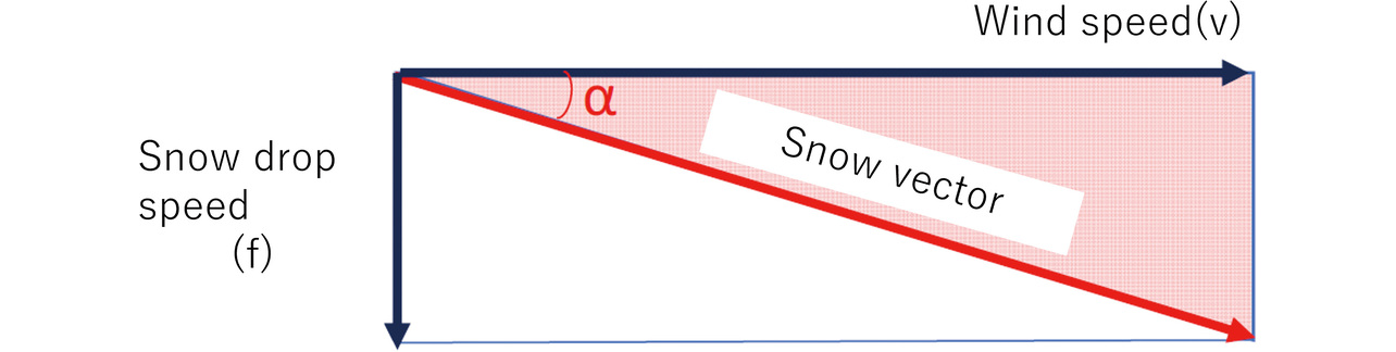
The existing literature reports that typical snow crystals fall at a speed of 0.94 m/s8). We adopted a simple theoretical model that represents the flying direction of snow particles as the relationship of the vertical fall velocity of snow particles (f) and wind speed (v) with the horizontal-wind vector factored in. Then, the incidence angle at which snow particles fall to the sensor surface is represented by Eq. (1) and Fig. 3. For convenience and simplicity, let the fall speed be converted to 1 m/s, for example. Then, for a wind speed of 10 m/s, the incidence angle to the sensor surface turns out to be 5.7 degrees (°). Note that, for simplification, this model does not consider winds that blow up from downwards.
2.3 Determining the preliminary geometry of the hood
We considered the hood using a theoretical model for the flying direction of snow particles. To ensure that radio-wave irradiation from the millimeter-wave radar is not blocked by snow accretion when the hood is applied to the millimeter-wave radar, we had to explore a structure that prevents snow adhesion to the printed circuit board (hereinafter “radar antenna board”) area, including the radar’s transmitting and receiving antennas. Fig. 4 shows the model mentioned above. Then, the detection limit angle β for snow adhesion to the bottom edge of the radar antenna board is expressed by the parameters and Eq. (2) given below. When Eq. (1) and the dip angle θ of the millimeter-wave radar are factored in for this angle, Ineq. (3) theoretically holds. In other words, if the Theoretical Inequality (3) is satisfied, no snow accretion occurs above the bottom edge of the radar antenna board, which means that no problem occurs with radio-wave transmission and reception.
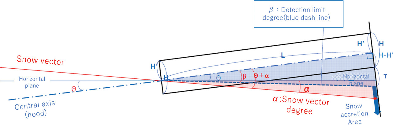
Fig. 5 shows the preliminary geometry we designed for the hood based on these parameters.
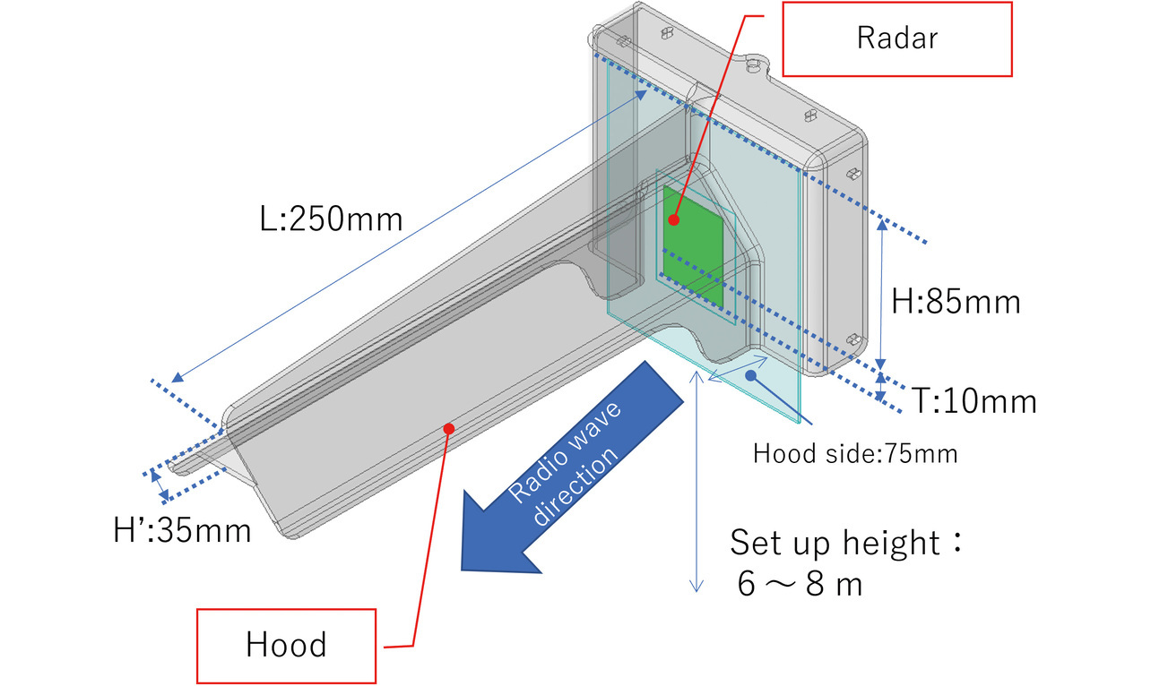
Regarding the hood’s material, we adopted polycarbonate, the same material used for a radio-wave irradiation surface cover (hereinafter “radome”) with known characteristics, out of consideration for radio waves’ permeability and the elimination of disturbance factors in the simulation.
- H: Hood height (mm)
- H′: Apron length (mm)
- L: Hood length (mm)
- T: Length to the underside of the radar antenna board (mm)
- θ: Dip angle of the millimeter-wave radar (°)
3. Detailed geometry design of the hood
The preliminary hood geometry from Section 2 was designed solely to address snow accretion on the millimeter-wave radar without considering the influence on the radio-wave transmission and reception by the millimeter-wave radar. Significant changes in the radio-wave characteristics due to the added hood may affect the vehicle detection performance. Hence, we decided to simulate and estimate the influence of the hood geometry on the radio-wave characteristics to obtain a design with the influence reduced to the minimum.
3.1 Simulation conditions
We analyzed the hood geometry’s influence on the millimeter-wave radar’s radio-wave characteristics. For the analysis, we used the Ansys HFSS electromagnetic field simulator. Fig. 6 (a) shows the analysis model of the millimeter-wave radar alone with no hood on it. Note that for the sake of a reduced computational load, this analysis model consists only of the following two components, which have a significant contribution to the characteristics of the radio wave transmitted and received by the radar:
- Radar antenna board
- Portion of the radome
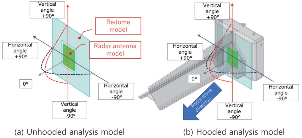
Meanwhile, Fig. 6 (b) shows the analysis model with the hood on it.
We analyzed these models, one before and the other after the addition of the hood, to compare and evaluate their antenna radiation patterns in the horizontal and vertical planes. An antenna radiation pattern with a lower gain reduces the vehicle detection range of the millimeter-wave radar. The angle width in a radiation pattern with a gain reduced to half the maximum value is called the beam width. A reduced beam width narrows the vehicle detection angle range, leading to fewer lanes available for vehicle detection. Therefore, a smaller change in the radiation pattern due to the added hood will affect vehicle detection performance less.
3.2 Simulation results
When the millimeter-wave radar’s installed form and relative position to the detection target vehicle are considered, as viewed from the millimeter-wave radar, the detection target vehicle can only exist in the range where the analysis models in Fig. 6 have a zero or sub-zero degree vertical angle. The hood is shaped with a vertical angle wide open to the minus range. As a result, in the simulation, neither the gain nor the beam width showed any clear-cut change within the range concerned in the vertical plane. Therefore, the hood length L, an influencing factor in the vertical direction, was fixed to 250 mm and excluded from our consideration here. We limited our evaluation to the horizontal-plane radiation patterns.
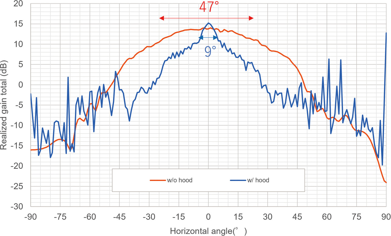
Fig. 7 shows the simulation results for the horizontal-plane radiation patterns at the millimeter-wave radar’s operating frequency of 76 GHz. The hooded model shows its horizontal angle reduced from 47° to 9°, nearly fivefold down relative to the value achieved by the unhooded model. A fine oscillatory component is superimposed on the radiation pattern of the hooded model. This component, called ripple, occurs due to radio-wave multipath reflection on the hood. The change observed here leads to a reduced vehicle detection range or fewer lanes available for vehicle detection.
3.3 Improving the hood
It is critical to identify the cause of the influence of the hood presented in Subsection 3.2 to minimize it. The influence occurred when a region of the hood surface reduced the directivity of the radio wave. Therefore, we identified the region responsible and considered giving it an improved shape that would not reduce the directivity of the radio wave. During this consideration, we surmised that the primary factor affecting the horizontal-plane radiation pattern would be found in the geometry of the hood side wall portions disposed orthogonally to the horizontal plane. The hood must protect against winds and snow from the direction of its side walls. Hence, we explored the possibility of adjusting the side wall length to minimize its influence on the radiation pattern while retaining the side wall portions per se. As an exploration method, we prepared a model with its hood side portions’ length adjustable to 40, 50, 60, and 70 mm from the radome surface as shown in Fig. 8 (a). Then, we compared the influences of length adjustments on the horizontal-plane radiation pattern.
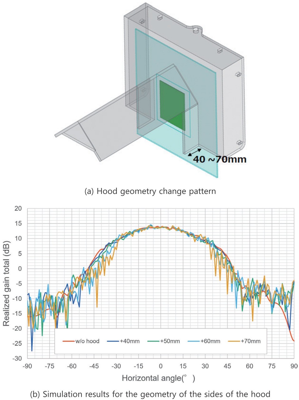
Fig. 8 (b) shows the obtained results. These results revealed that when set to 50 mm or more, the side wall length clearly intensified its influence on the beam width, which resulted in increased ripple. Accordingly, we decided on a side wall length of 40 mm.
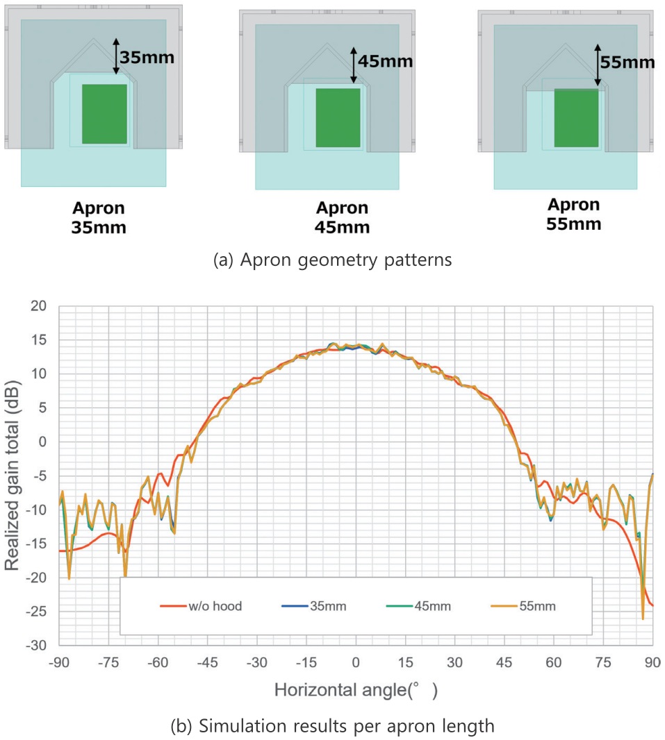
Meanwhile, as a snow accretion prevention mechanism, the hood’s apron portion should preferably be structured to cover and hide the radar antenna board as much as possible. Therefore, we simulated with its length adjusted to 35, 45, and 55 mm as shown in Fig. 9 (a). Fig. 9 (b) shows the obtained results. These results showed that apron length did not significantly affect the radiation pattern. Hence, we left the length decision to the final snow accretion experiment.
4. Snow accretion experiment
Based on the electromagnetic field simulation in Section 3, we determined a hood geometry free of influences on the directivity of the radio wave. This section presents the snow accretion experiment performed using the hood of the obtained geometry to see if the snow would accrete to the radar antenna part.
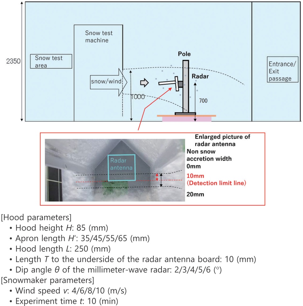
4.1 Experimental conditions
Fig. 10 shows the experimental conditions of the snow accretion experiment. Using a snow-making machine able to reproduce winds blowing at speeds up to 10 m/s, we blew snow at a hooded millimeter-wave radar installed on the fixed pole at the center of Fig. 10. As regards the experimental conditions for the hood, H′ and θ were adjusted as specified in Fig. 10. Using the snow-making machine with an adjustable wind speed v, we performed snow blowing. The pass/fail decision was made based on whether or not snow adhered to the radar antenna board area of the millimeter-wave radar after the lapse of a certain experiment time. Note that the experiment was performed not to exhaustively cover the entire value ranges of all the experimental parameters but to search for parametric values sufficient to achieve the pass-threshold wind speed of 10 m/s. Regarding the type of snow for the experiment, we decided on wet snow, which most easily adheres to the millimeter-wave radar.
4.2 Experimental results
Fig. 11 shows the results of the snow accretion experiment. As expressed by Theoretical Equation (2), the X-axis in Fig. 11 defines the incidence angle β of radio wave incident on the bottom edge of the radar antenna board with the millimeter-wave radar fitted with the hood and laid in the horizontal position. In this experiment, the angle β was variable by adjusting the apron length. The Y-axis dip angle θ + α was the approach angle α for snow particles factoring in the dip angle of the millimeter-wave radar, whereby to be variable by adjusting the wind speed and the radar dip angle. The experimental results are plotted as “OK,” “Marginally OK,” and “NOK” points with respect to the Y- and X-axis angles determined by changing these parameters. The points marked “OK” represent the experimental conditions under which no snow accretion was observed above the bottom edge of the radar antenna board shown in Fig. 10. The points marked “Marginally OK” represent the experimental conditions under which no snow accretion was observed above the line 10 mm from the bottom edge of the radar antenna board. The justification for the 10 mm is given by a 10 mm clearance extending from the bottom edge of the radar antenna board to the antenna element portion related to transmission and reception. The clearance was defined as the limit for keeping the radio-wave characteristics unaffected. Finally, the points marked “NOK” represent the experimental conditions under which heavier snow accretion occurred than under the “Marginally OK” experimental conditions.
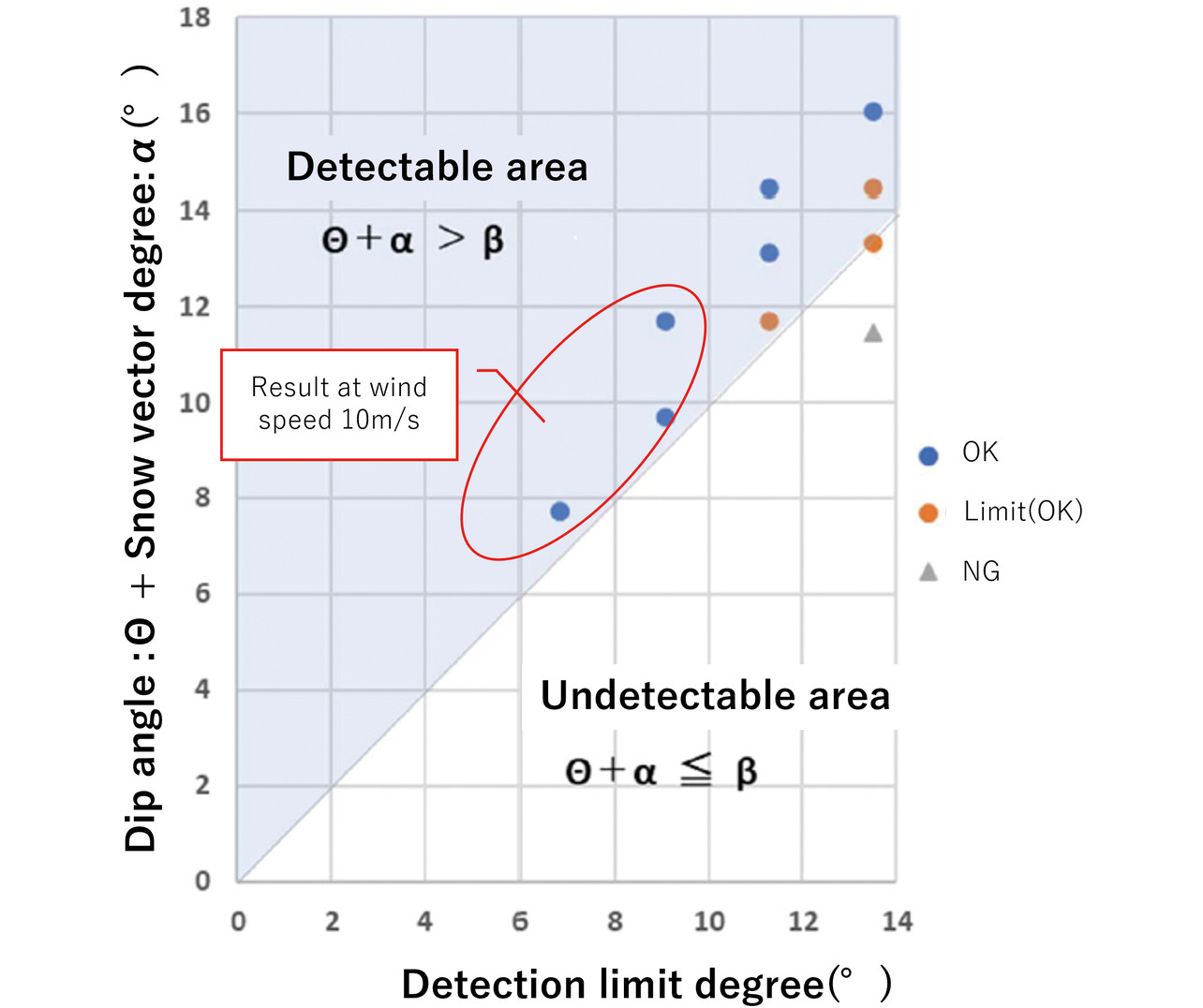
The graph plotted with these results is segmented into detectable and undetectable areas based on Theoretical Inequality (3). These segmented areas are theoretically explained as follows: Assuming that the parameters given for Theoretical Inequality (3) are correct, the following will hold:
- Detectable area: An area in which snow accretion on the bottom edge of the radar antenna board is expected
- Undetectable area: An area in which snow accretion above the bottom edge of the radar antenna board is expected
The results show that the NOK points lie in the undetectable area while the Marginally OK points lie almost on the boundary, revealing that the experimental and theoretical values are in close relationship. Note that the points plotted within the red-encircled area in Fig. 11 are the experimental results obtained at a wind speed of 10 m/s, represent snow accretion that occurred below the radar antenna board, and are found OK. As such, these results are found sufficient to meet the snow accretion prevention performance required of the hood presented herein.
5. Real-field verification
The experiment described in Section 4 led us to complete a hood that does not reduce the directivity of the radio wave and can withstand snow-laden winds blowing at the target speed of 10 m/s. For the purpose herein, we performed a vehicle detection experiment in an actual field as a final verification step.
5.1 Experimental conditions
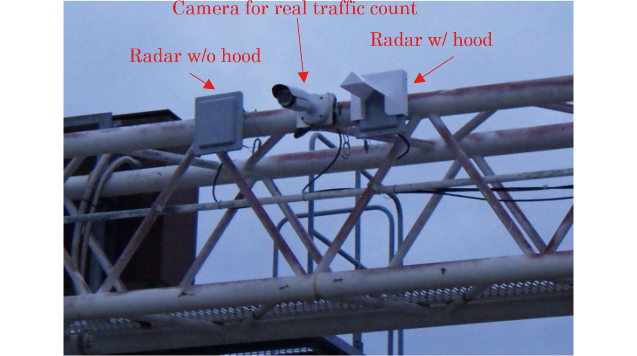
As shown in Fig. 12, we physically experimented with on-road vehicle detection to see if vehicle detection would remain unaffected with a hood fitted on the radar. The experiment was performed by operating a pair of time-synchronized millimeter-wave radars (hooded/unhooded) and a camera for true traffic counting to compare the detected traffic counts obtained by the millimeter-wave radars with the true count.
Other experimental conditions are as follows:
- Installed height of the millimeter-wave radar: 5.85 m
- Number of experimental lanes: 4 lanes
- Direction of vehicle detection: Distancing direction (rearward detection)
- Vehicle detection position: 60-meter point from the sensor
5.2 Experimental results
The experimental results in Table 2 show the vehicle detection counts and accuracies obtained by the unhooded and hooded millimeter-wave radars.
| True traffic count by the camera | Detected traffic count | Detection accuracy | |
|---|---|---|---|
| Unhooded millimeter-wave radar |
644 vehicles | 661 vehicles | 97.4% |
| Hooded millimeter-wave radar |
645 vehicles | 99.8% | |
Note that the detection accuracy values in Table 2 were calculated using Eq. (4). The results reveal that the hooded millimeter-wave radar showed detection accuracy higher by 2.4 points than its unhooded counterpart. These results confirm that the intended accuracy was achieved, albeit a difference in accuracy between the two conditions.
Our hooded millimeter-wave radar demonstrated higher detection accuracy than its unhooded counterpart. The probable contributing factors to this achievement may include the following possibilities:
- The hood may have successfully cut the unwanted multipath radio wave reflections returning to the millimeter-wave radar from outside the intended lanes and elsewhere. Before designing the hood proposed herein, we evaluated the transmitting antenna by simulation regarding radiation pattern. However, we did not evaluate the receiving antenna.
- The radio-wave irradiation to the target object and the reflected wave reception vary depending on the object’s relative position to the installed positions of the hooded and unhooded millimeter-wave radars. Hence, slight errors may have occurred.
Incorporating the factors considered above, we concluded that the hooded millimeter-wave radar matches its unhooded counterpart in terms of achievable detection accuracy.
6. Conclusions
In this report, we considered and determined the following method of protecting millimeter-wave radars from the challenge of snow accretion on their surfaces. First, we compiled nationwide data on snow-laden wind speed, which allowed us to specify a target value of 10 m/s for the speed of snow-laden winds to be guarded against. In the subsequent hood development phase, we successfully determined by radio-wave simulations a hood geometry that contained no negatively affecting factors and prevented the hood itself from blocking the millimeter-wave radar’s radio wave. Then, we performed a snow accretion experiment for the obtained hood geometry, thereby demonstrating that the radar antenna board area remained free of snow accretion even under snow-laden winds blowing at the target speed of 10 m/s. Then, we finally verified using actual vehicles on real roads to confirm that the millimeter-wave radar with the hood on it provided the same detection accuracy as its unhooded counterpart.
The above efforts led us to develop a hood that features a windproof/snow-proof mechanism for withstanding the steady snow-laden wind speed and simultaneously provides a radio-wave irradiation range that does not affect vehicle detection.
There was also a side benefit: no rework was needed to verify the development of the hood presented herein. One of the factors responsible was that we developed a theoretical model of the mechanism of snow accretion and determined the detailed geometry of the hood by electromagnetic field simulation in preparation for the experiment, which allowed us to omit the conventional cut-and-try process of making improvements based on the feedback from experimental results.
Moving forward, we plan to deploy our millimeter-wave radars fitted with the hood presented herein to snowy regions where millimeter-wave radars are supposedly challenging to install with conventional hoods.
References
- 1)
- National Council for Traffic Safety Measures. “The 11th Traffic Safety Basic Plan.” (in Japanese), Cabinet Office of Japan. https://www8.cao.go.jp/koutu/kihon/keikaku11/index.html (Accessed: May. 17, 2024).
- 2)
- Specifications for Traffic Detectors, NPA Traffic Eqt. Spec. No. 1017 “Ver. 2”, (in Japanese), 2019-03-13.
- 3)
- Traffic Bureau, National Police Agency (Gen. Ed.), in ITS Developed by Japanese Police, (in Japanese), Japan Traffic Management Technology Association and Institute of Urban Traffic Research, 1998, pp. 44-45.
- 4)
- Y. Tanimoto et al., “Millimeter-Wave Traffic Monitoring Radar using High-Resolution Direction of Arrival Estimation,” (in Japanese), OMRON TECHNICS, vol. 52, no. 1, pp. 41-46, 2020.
- 5)
- R. Fujimori et al., “Traffic Signal Split Control Method Using Spring Model,” (in Japanese), IPSJ SIG Technical Report on Mathematical Modeling and Problem Solving (MPS), 2021-MPS-136, no. 2, pp. 1-6, 2021.
- 6)
- Statistics Bureau, Ministry of Public Management, Home Affairs, Posts and Telecommunications. “Prefectures as Revealed by Statistics 2021 (B: Natural Environment).” (in Japanese), e-Stat. https://www.e-stat.go.jp/stat-search/file-download?statInfId=000032055319&fileKind=0 (Accessed: Jun. 13, 2024).
- 7)
- Japan Meteorological Agency, Ministry of Land, Infrastructure and Transport. “Past Weather Data Download.” (in Japanese), Japan Meteorological Agency, Ministry of Land, Infrastructure and Transport. https://www.data.jma.go.jp/risk/obsdl/index.php (Accessed: Jul. 17, 2023).
- 8)
- C. Magono, “Falling Velocity of Snow Crystals,” (in Japanese), J. Japanese Soc. Snow and Ice, vol. 15, no. 6, pp. 1-4, 1954.
The names of products in the text may be trademarks of each company.