


Simulation technology to predict dynamic motion of relay
- Coupled analysis
- Dynamic motion analysis
- Contact bounce
- Breaking velocity
- High capacity of relay
It is very important for design to predict the dynamic motion of contact for realizing downsizing and high capacity for a mechanical relay along with trend of downsizing of application devices and saving energy.
In order to predict the dynamic motion of contact, first, it is possible to obtain the displacement of the movable part of the electromagnet for each time history in electromagnetic analysis, and then it will be achieved by coupling the calculated time and displacement with the structure analysis of movable contact part.
As a result of considering the method of coupled analysis from electromagnet to contact motion and the analysis accuracy with using two CAEs at this time, we established the method of verification by relative comparison of the dynamic motion such as contact bounce and breaking velocity of electric contact. It will be possible to predict the motion due to structural change before prototypeing, and realize the narrowing down of trial evaluation and shortening the lead time.
By deployment to the actual design in specific models and controlling the breaking velocity, we doubled the electrical endurance for the products with high capacity of 1.5 times higher than the past.
1. Introduction
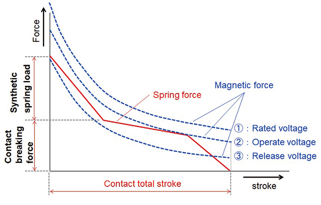
The relay is a device to switch on and off the electric circuit according to the electric signal received from the outside. In the case of mechanical relays, the electric signal received is converted into a magnetic force by the electromagnet, and the electric contact is mechanically switched on and off by the magnetic force through the contact operating mechanism. Actuation of the relay is determined by the balance of the spring force (spring load) and the magnetic force of the electromagnet (magnetic force) in the contact operating mechanism, and when the magnetic force approaches the spring load, the contact operating mechanism in the release condition starts to move, and the contact is engaged when the magnetic force exceeds the spring load1). Fig. 1 is the graph showing balance of the magnetic force and spring load (design for static actuation) in the actuation stroke.
As explained above, actuation of the mechanical relay depends on actuation of the contact operating mechanism when the circuit is turned on and off, and the transient operation of the contact operating mechanism will affect performance of the relay and may lead to a failure of the relay. Contact weld, for example, which is a major failure mode in electrical durability evaluation, is a phenomenon caused by bouncing behavior of the contact (impacting) due to the bouncing force in making a contact. When the contact bounces, an arc (a type of electric discharge) is produced, and weld of the contact occurs due to melted material by the energy of the arc when the contact is made again2). Weld of the contact is removed if the force sufficient to pull off the weld is applied to the contact. The contact breaking force is statically important to pull off the stuck contact, and the contact breaking velocity in recovering affects the behavior in actuation. As explained above, the design of the transient behavior of the contact operating mechanism, in other words, the design of the dynamic behavior, is important in addition to the design of the balance between the magnetic force and spring load. In this study, the authors have established the simulation technique by the 3D CAE for the dynamic behavior affecting contact weld: (i) contact bouncing phenomenon in actuation behavior, and (ii) contact breaking velocity in releasing behavior. In addition, the relay with higher capacity is developed using the simulation technique.
2. Dynamic Behavior Design
2.1 Issues involved in existing method
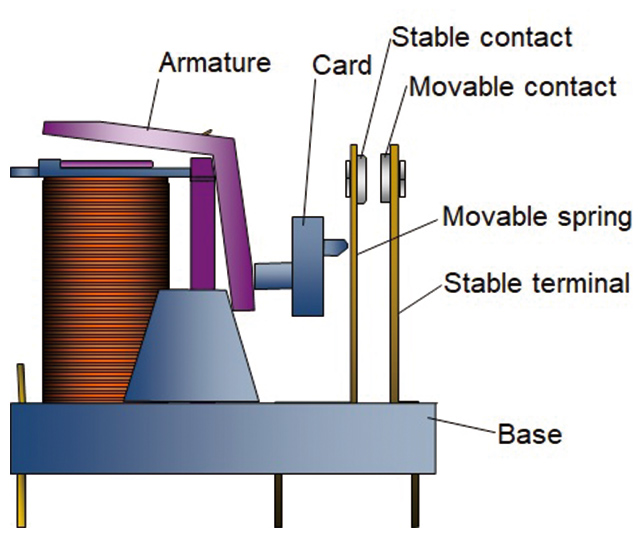
The method used for design of dynamic behavior is reported by S. Itoda, et al.3) The method uses the electromagnet analysis CAE to calculate the magnetic force of the electromagnet used to actuate the relay contact and quantifies the dynamic on/off behavior of the moving part of the electromagnet (armature) by simulation with the magnetic force and spring load. This method can be used when the armature and the contact are directly coupled, but because a commonly used relay as shown in Fig. 2 has a construction where the contact is actuated by the force from the armature transmitted by the part called the “card” and because the movable spring of the contact operating mechanism may deflect, the armature and the contact cannot move perfectly coupled. So in order to reproduce the transient behavior of the relay, the simulation technique combining dynamic behavior of the armature by electromagnet analysis and dynamic behavior of the contact operating mechanism by structural analysis is required.
2.2 Combining electromagnet analysis and structural analysis
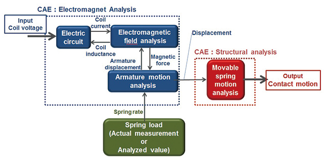
The detail flow combining the electromagnet analysis and structural analysis to make the behavioral simulation of moving part of the contact is shown in Fig. 3.
-
(i) Electromagnet analysis
Using the coil current as an input of the electromagnet analysis CAE, one can calculate the transient displacement of the armature as an output by transient coupling of the electromagnet and the spring load applied to the electromagnet. Simulation of behavior of the contact is made incorporating the output in the next step structural analysis. -
(ii) Structural analysis
The output information of the armature displacement obtained by the electromagnet analysis is used to make the time and displacement table, which is used as input information to be coupled with the structural analysis CAE. Transient behavior of the contact operating mechanism is simulated by providing the armature displacement information as the time-displacement information of the card actuating the movable spring.
2.3 Theoretical Interpretation of Coupled Analysis
Explanation of the process to calculate the contact behavior in the coupled analysis is given as follows:
-
(i) Electrical circuit
Current flowing through the electromagnet coil is calculated using Equation (1).
-
 (1)
(1)
-
 : Coil Voltage
-
 : Coil inductance,
-
 : Coil current
-
 : Coil resistance,
  : Time
-
(ii) Electromagnetic field analysis
Obtain magnetic flux density from the current obtained by Equation (1) and calculate the magneticforce
  generated at the moving part.
-
 (2)
(2)
-
 : Magnetic force of the electromagnet
-
 : Permeability of the vacuum
-
 : Magnetic flux density
-
 : Cross sectional area where magnetic flux penetrates
-
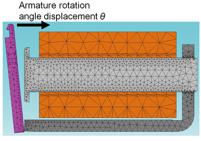
(iii) Motion analysis of armature
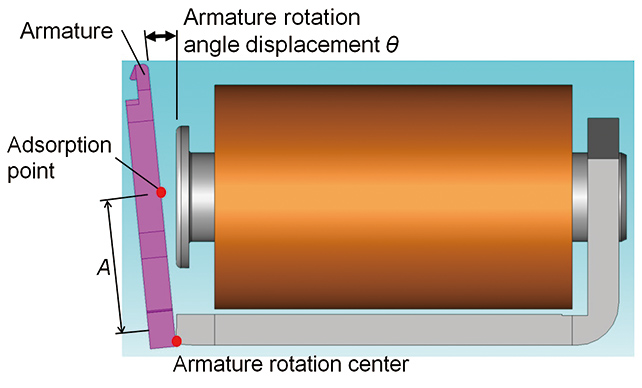
Substitute the magnetic force obtained by Equation (2) to the equation of motion (3) and obtain rotational angular displacement of the armature (see Fig. 4). Spring constant  used in Equation (3) needs to be obtained in advance by structural analysis CAE.
-
 (3)
(3)
-
 : Torque acting on the armature
-
 : Moment of inertia
-
 : Angular displacement of the armature
-
 : Distance from the center of rotation of the armature to the action point of magnetic force
-
 : Attenuation constant
-
 : Spring constant
-
 Change of with time can be obtained by repetition of (i) through (iii).
-
(iv) Motion analysis of movable spring
Time and displacement obtained by Equation (3) are converted to the displacement
  of the contact spring to obtain the equation of motion (4).
-
 (4)
(4)
-
 : Spring load
-
 : Mass of the contact
-
 : Viscous damping
When the equation of motion (4) is solved, the dynamic behavior of the contact can be calculated from the displacement of the card.
3. Analysis Results
Explanation of the results of analysis for the contact bouncing phenomenon in actuation and the contact breaking velocity in releasing that affect weld of the contact as described in Section 1 using the coupling flow shown in Fig. 3 are as follows.
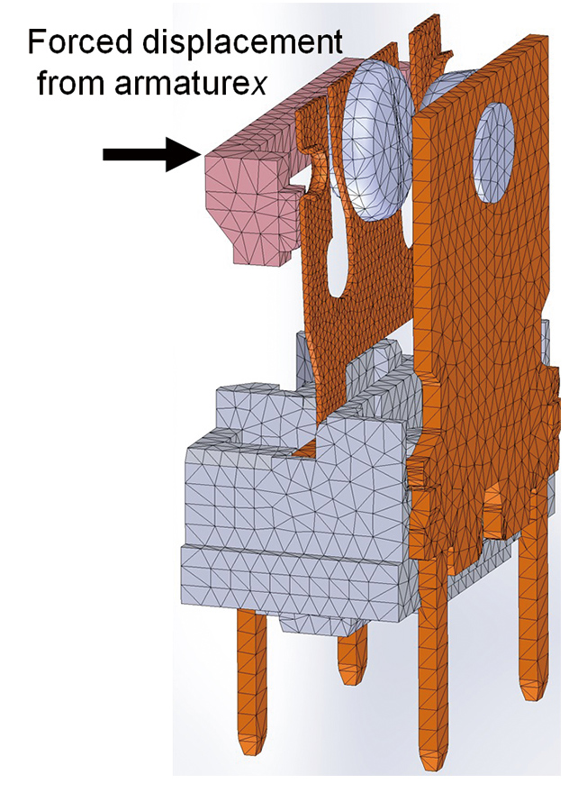
3.1 3D CAE Model
Figures 5 and 6 show the 3D CAE model used in the analysis. The electromagnet model is used to calculate the transient behavior of the armature and contact operating mechanism model is used to calculate the transient behavior of the contact. The contact operating mechanism consists of the card that transfers the transient behavior of the armature, the movable spring that opens/closes the contact according to the behavior of the card, the movable contact and stationary contact that connect and disconnect electrical signal, the stationary terminal that holds the stationary contact, and the base that holds the movable spring and stationary terminal.
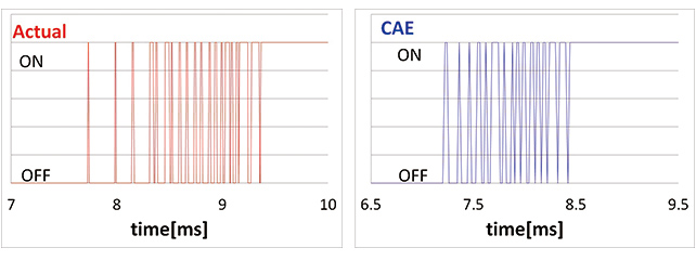
3.2 Analysis results of contact bouncing in making
Analysis results of the contact bouncing in making are explained in this subsection. Fig. 7 shows typical waveform of bouncing measured and the analysis results. The waveform measured was obtained by measuring the voltage between terminals when the relay is activated using the oscilloscope. In addition, Table 1 shows the number of times the contact bounced and the comparison of the measured values and analysis values for the bouncing time when the relay is activated for the waveform shown in Fig. 7. When the bouncing waveforms in Fig. 7 are compared, the analysis result reproduces the peculiarities of the measured waveform fairly well, such as the cycle of bouncing immediately after the contact bouncing started is longer than the cycle after bouncing is repeated. As shown in Table 1, errors in the number of bouncing of the contact analyzed are 20% to 30% compared with the measurement.
| Actual value | Analyzed value | Accuracy | |
|---|---|---|---|
| Number of Bounce | 20times | 16times | 20% |
| Time of Bounce | 1.64ms | 1.22ms | 26% |
Next in Table 2, the measured values and analysis values are shown for the times of bouncing and the accuracy of the analysis for the contact bouncing in making when the contact push stroke after the relay makes contact (contact follow) is changed. As the contact bouncing time increases when the contact follow increases both in the measurement and in the analysis, and as the accuracy of the analysis compared with the measurement is stable with a 20% to 30% difference, it is considered that the simulation technique can be used satisfactorily as the relative evaluation.
| Time of Bounce | Contact follow | ||
|---|---|---|---|
| Low (63%) | Reference (100%) | High (150%) | |
| Actual value | 1.34ms | 1.64ms | 2.13ms |
| Analyzed value | 0.94ms | 1.22ms | 1.64ms |
| Accuracy | 30% | 26% | 23% |
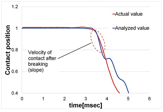
3.3 Movable contact actuation analysis results in releasing
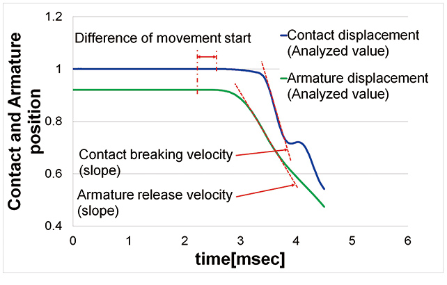
Next, the analysis results of the movable contact actuation behavior are explained. The release condition is with the surge absorbing diode connected to the electromagnet coil. Fig. 8 is a graph showing the measured values and the analysis results for transient displacement of the movable contact vs. time in releasing. The numbers on the scales of the ordinate are indicated with the full stroke of the contact (see Fig. 1) as 1.0. The measured value is obtained by analysis of the image data of the high-speed camera. When the contact behavior waveforms from the measurement and by analysis are compared, both the analysis and measurement data show the same trend in the timing when the contact breaks and in the behavior after contact breaking, and while there is about a 19% difference between the contact breaking velocity by measurement and by analysis (average slope of the curve encircled in oval of red dashed line in Fig. 8), it is within the level for use in a relative study of the contact breaking velocity. Conversely, there is a difference in the timing where the breaking velocity decreases in releasing behavior of the contact, and it is an issue to be resolved to improve the accuracy of the analysis with respect to the vibration mode of the movable spring after contact breaking.
3.4 Comparison of movable contact behavior and armature behavior
In the case of a relay that has a construction where electromagnet behavior is transferred to move the elastic movable spring via the card like the 3D CAE model used in this study, the armature behavior is not coupled with the contact behavior, and in order to confirm such uncoupled behaviors, transient behaviors of the movable contact and the armature are compared in Fig. 9. The movable contact behavior used is the analysis results in Subsection 3.3. For the armature behavior, the method by Itoda et al.3) is used, and the accuracy of analysis comparable to that of the report (5% or less) is confirmed. As shown in Fig. 9, there is a difference between the timing of the contact and the armature, and the difference between the contact breaking velocity and the armature release velocity is about 2.1 times, which indicate that the contact behavior and the armature behavior are not coupled. Accordingly, the coupled analysis of the electromagnet analysis and structural analysis is required for the relay having such a construction.
4. Application for product development of high capacity relays
Needs for high capacity relays compared with the existing products are increasing in the market because of the trend for smaller devices and energy saving. In order to meet such needs, development of the product targeting the equal size and power consumption as the existing relay but capable of making and breaking current capacity of about 1.5 times was undertaken first in the industry.
When a high current load is operated by the existing relay, weld of the contact will occur very soon. This is because contact welding force increases due to increased contact melting by increased arc energy associated with the high current, and the contact becomes unable to be released by the existing force available. So to realize the high capacity relay, improvement of the contact welding force and the contact-releasing force is required. As a measure to improve the contact-releasing force, the authors focused on the contact breaking velocity, and studied the construction required to increase the contact breaking velocity by minimum modification of construction using this contact behavior simulation technique.
4.1 Condition for contact behavior analysis
As explained in Section 1, actuation of the relay is determined by the balance of the spring load and the magnetic force statically. On the other hand in the case of a circuit where a diode is connected in parallel to the coil for surge current protection of the coil, a magnetic force is generated when the contact is released because the current flowing through the coil gradually decreases. So a change in the difference between the spring load and the magnetic force with time is important dynamically. Based on the considerations above, the conditions for the study of contact breaking velocity were investigated from the aspects (i) to increase the spring load after the movable contact makes with the stationary (combined spring load: see Fig. 1) and (ii) to reduce magnetic force in releasing.
In the study, construction and power consumption of the electromagnet were set the same as the existing relay and optimization of the breaking velocity only by a change of contact operating mechanism was pursued.
-
(i) To increase combined spring load
A method to change parameters related with the spring load without changing the geometry of the movable spring and the stationary terminal (geometry of the spring), or a method to change geometry of the spring to increase spring constant of the synthetic spring can be considered. -
(ii) To reduce magnetic force in releasing
It is known that the magnetic force in releasing is affected by actuation of the armature. When the timing of the armature actuation is advanced, the coil current at that time increases, which leads to increases of the magnetic force in releasing. So, the magnetic force in releasing can be reduced by decreasing the combined spring load.
As the above (i) and (ii) are conflicting requirements, the combined spring load and shape of the spring used are according to the pattern as shown in Table 3. The combination of high combined spring load and spring shape change was not included in the study because of the stress design.
| Combined spring force | Spring shape | |
|---|---|---|
| Without modification | With modification | |
| High (100~150%) | ・Parameter A | ― |
| Low (50~100%) | ・Parameter B ・Parameter C |
・Spring rate low A ・Spring rate low B |
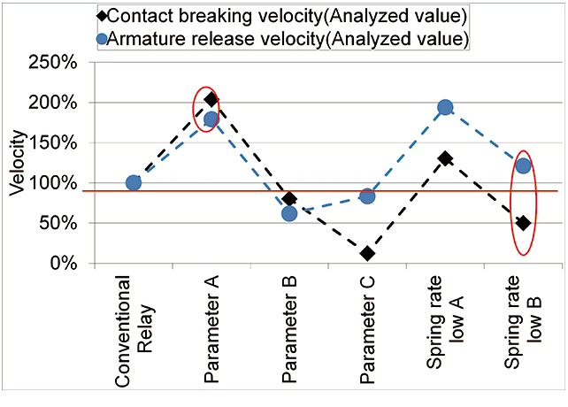
4.2 Analysis results
Fig. 10 shows the results of analysis of the contact breaking velocity and the armature release velocity in releasing according to the patterns in Table 3. The results are shown in relative values to the analyzed velocity of the existing relay as 100%. As shown in Fig. 10, changes of the contact breaking force and armature release velocity occur similarly like parameter change A or occur conversely like spring constant low B, and it is confirmed that the contact breaking velocity and armature release velocity are not coupled. It was also confirmed that magnitude of the combined spring load and contact breaking velocity are not correlated.
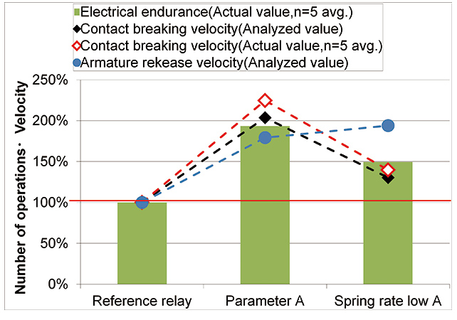
4.3 Evaluation using actual relay
Electrical endurance using the prototype were conducted for two conditions, parameter change A and spring constant low A, which will be effective to contact breaking velocity and armature release velocity according to analysis results in Fig. 10. Fig. 11 shows the results of electrical endurance, measured values, and analysis values of the contact breaking velocity, as well as the analysis results of the armature release velocity relative to the values of the reference relay. The reference relay is the existing relay with its adhesion improved. As shown in Fig. 11, the trends of the contact breaking velocity and electrical durability are very similar, and in the case of parameter change A where contact breaking force is about twice in the analysis, the number of relay operations is also twice. The analysis value of the contact breaking velocity is also consistent with the measured value. Conversely, trends of the armature release velocity and electrical durability are not consistent. The results show that performance improvement can be effectively made by predicting the contact breaking velocity using behavioral analysis.
5. Conclusion
In order to meet the needs for high capacity mechanical relays, effective design of the contact behavior in making and release is important. So far, evaluations by measurement of the prototype have been made but various issues, such as the time required to make the prototype, restrictions in the evaluation pattern, and wide variability in accuracy of the prototype, were involved. Furthermore, the existing simulation technique cannot analyze behavior of the contact by the CAE only where the electromagnet and the contact operating mechanism are not directly coupled.
By constructing the simulation technique of the contact bouncing behavior in making and contact breaking velocity in release that are important parameters of the contact actuation behavior in this study, prediction of the change in the actuation behavior becomes possible before fabrication of the prototype. This will contribute to narrowing feasible prototypes and reduction of lead time. When the simulation technique was applied to the development of high capacity relay, the condition where the number of relay operations can be extended almost twice without changing construction of the electromagnet and power consumption can be found before making a prototype. It was demonstrated that the idea to increase the force to release the contact by increasing the contact release velocity was effective. The authors consider constructing more versatile technique such as to improve accuracy in estimating the velocity change after contact breaking that cannot be sufficiently reproduced in this study and to allow behavioral analysis after electrical durability evaluation.
References
- 1)
- Nippon Electric Control Equipment Industries Association. “Basics of Control Equipment (Methods of Use and Selection) - Relays General”. NECA. https://www.neca.or.jp/wp-content/uploads/CU_Ry_2%20Sou_1803.pdf, (accessed on 2019-01-25) (in Japanese).
- 2)
- Takagi, T. Arc Discharge Phenomenon of Electrical Contact. Corona Publishing Co., Ltd., 1995,p.79-81, p.99-102 (in Japanese).
- 3)
- Itoda, S.; Nishida, T. Dynamics simulation technology for high electrical durability relay. OMRON TECHNICS. 2018, Vol.50, No.1, p.68-73 (in Japanese).
The names of products in the text may be trademarks of each company.