


Development of the Vibrate Reproduction Software for Vibration Sensors
- Verification Technology
- Earthquake
- Simulation
- Acceleration
- Vibration Sensors
The Great Hanshin-Awaji Earthquake of 1995 and the Great East Japan Earthquake of 2011 resulted in a large-scale disaster, such as building collapses and fires. Therefore, it is recognized that the grasp of building damage is important for the early reconstruction of the region and infrastructures1), and s method is required. OMRON has been providing vibration sensors for many years made of steel balls2) that detect earthquakes, but in order to meet this need, we have released a vibration sensor equipped with an algorithm that analyzes vibrations and quantifies building damage levels, which also improved earthquake detections and realized a free mounting direction3). This vibration sensor analyzes vibrations with an accelerometer, and an accelerometer produces continuous digital data from the vibrations. So, the most important point for evaluating the accuracy of vibration sensors is the accurate reproduction of vibrations.
The earthquake vibration waveform will be different depending on the epicenter, energy, and observation site conditions; unpredictable vibration sensors are tested with various waveforms for unpredictability. Reproduction of these vibrations and waveforms are produced by vibration test systems with large-size actuators. However, it is not easy in terms of time and cost to reproduce accurate vibrations of many earthquake waveforms because of the variety and complexity.
Therefore, instead of verification of the vibration test systems, we developed software to reproduce the vibrations of waveforms and reproduce our vibration sensors embedded in the software simultaneously. This made it possible to examine in a shorter time with greater efficiency the verification of our vibration sensors with various vibration waveforms including earthquakes.
1. Introduction
Since large earthquakes that occurred frequently in recent years caused large-scale damage to buildings and structures, a detailed grasp of the damage status is very important in order to reconstruct the local community at an early stage. The detailed grasp of the place of disaster occurrence enables early and precise determination of the place requiring reconstruction. Therefore, installation of a seismometer in each household enables the grasp of a disaster in each building and household in addition to the grasp of seismic intensity and disaster in each district by conventional intensive seismometers in each station of the Meteorological Agency.
OMRON has been providing vibration sensors for many years made of steel balls that have detected earthquakes. Although power consumption is low and battery consumption can be suppressed by these sensors that are of a mechanical type, they only detected a certain scale of large earthquakes. In addition, they sometimes could not detect even large-scale earthquakes because they determined earthquakes based on acceleration, and the actuation accuracy was not high due to the low correlation between acceleration and seismic intensity. We have performed the development of vibration sensors equipped with an algorithm for analyzing earthquake vibrations using a micro controller unit (MCU) and quantifying the disaster status of buildings to further improve the accuracy of earthquake analyses in the requirements of desiring the acquisition of not only the seismic intensity in each region but also the magnitude of an earthquake in each household.
In order to verify the developed algorithm for earthquake determination, the various verifications using a system for reproducing the vibration called a vibration test equipment are necessary. First, an earthquake that occurred in the past is reproduced using the vibration test equipment, and the scale of the earthquake transmitted by a vibration sensor is verified. Second, the prevention of the erroneous determination by the vibration sensor is verified by reproducing vibrations in the living environment. In order to reproduce the vibrations of an earthquake waveform, a large-size vibration test equipment system is generally used. The waveform greatly varies in each region depending on the ground in the region where an earthquake occurs and the distance from the place where an earthquake occurred. It is not easy from the viewpoints of time and expense to realize such an earthquake waveform inherent to each region with high reproducibility for an earthquake waveform in every region. In addition, it is not easy to reproduce a variety of vibrations because the daily life vibration is a shock, namely a sharp vibration, and it cannot be reproduced by a vibration test equipment that reproduces a periodic vibration, and the preparation of dedicated jigs having features suitable for each targeting vibration is required in order to reproduce stably.
Therefore, we developed reproduction software for simulating the behavior of a vibration sensor this time. This reproduction software can simulate vibrations without changing the embedded program of a product, and this is the first approach by us in the industry. Furthermore, we will compare and evaluate the tests that were so far conducted using a large-size vibration test equipment and the simulation calculation by reproduction software.
2. Vibration sensor and its mechanism
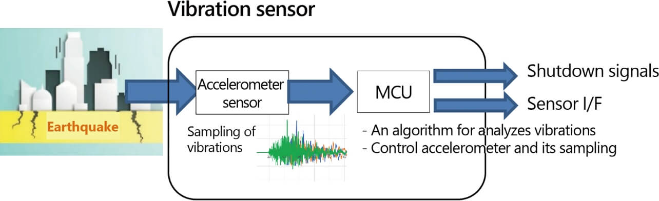
The vibration sensor developed by OMRON consists of a three-axis acceleration sensor and MCU equipped with a unique SI (spectral intensity) value calculation algorithm as shown in Fig. 1. The SI value is a quantity proposed by G. W. Housner in the US and obtained by digitizing the damage to buildings caused by earthquake vibrations and is defined by equation (1) as an average of the spectrum values in the period range from 0.1 s to 2.5 s in response speed of the earthquake waveform (unit is kine (cm/s)). In addition, it is known that a high correlation to seismic intensity class representing the magnitude of an earthquake is shown4,5). The vibration sensor digitizes the vibrations and oscillations from an earthquake by a three-axis sensor and transmits the SI values by processing the vibration data with the unique algorithm for SI value calculations. Furthermore, it has interrupt output signal for shutting down the customer’s devices when the SI value exceeds a certain large output. A general SI value is expressed by a mathematical equation and the calculations need high capacities and performance like PC’s CPU (central processing unit) that can perform highly functional operation processing is available. On the other hand, the processing ability is insufficient when a comparatively small-scale MCU is used. Our sensor enabled processing by a comparatively small-scale MCU using the algorithm that reduces the amount of earthquake calculation processing. In addition, it is equipped with a unique algorithm for detecting the vibration by shocks other than the earthquake and daily life vibrations, and it realized the prevention of erroneous detection not handled as an earthquake in that case.
The unit realized earthquake detection reproducibility with higher accuracy while having the above function, realizing the small module shape capable of surface mounting and the low power consumption behavior, and being equipped with an interrupt output signal performing an operation equivalent to the conventional steel ball vibration sensor to secure interchangeability with the steel ball vibration sensor.

- SI : Spectral intensity value
- Sv : Velocity response spectrum
- T : Period
- h : attenuation constant
3. Conventional verification method and task
3.1 Verification method by vibration test equipment
SI value accuracy verification in a vibration sensor is performed by reproducing the vibration waveform from the earthquake in the past by the vibration test equipment and various vibration waveforms from the daily environment. And as a result the SI values will be obtained from the sensor via accerelometer that received its earthquake or vibration waveforms. The consistency between the SI value calculated inside the accerelometer and the theoretical value calculated by equation (1) has been verified.
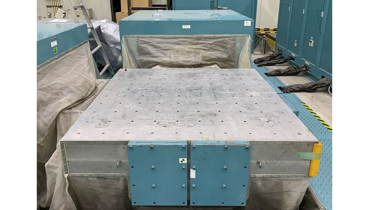
There are many types of vibration test equipment, such as large-size ones for shaking a house famous in CMs, simplified ones using a small-size servomotor, and ones that apply vibrations accurately suppressing shaking energy by being limited to one axis. In the conventional development, considering the balance of cost and verification speed, the verification was mainly performed using a simplified verification equipment using a three-axis small-size servomotor and a one-axis vibration test equipment with high accuracy, and a large-size vibration test equipment (Fig. 2) was used in the crucial case to implement the proper evaluation.
Data that were obtained by observing an actual earthquake in the past is used for the signal for driving the vibration test equipment as shown in Fig. 3. The data observed by vibrometers installed all over Japan by government offices, such as the Meteorological Agency, are often used to obtain these data.
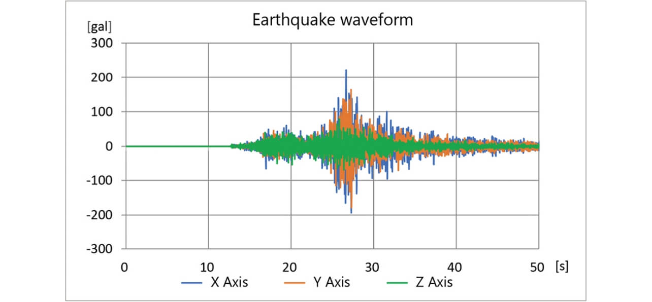
Fig. 4 shows the vibration test equipment. Earthquake data are entered into a vibration test equipment controller as an earthquake waveform, and a motor is driven to generate the vibration of the equipment. The vibration sensor that received the vibration by the equipped accelerometer, and SI values are calculated by the MCU. After the end of the vibration, SI values provided by the vibration sensor are checked.
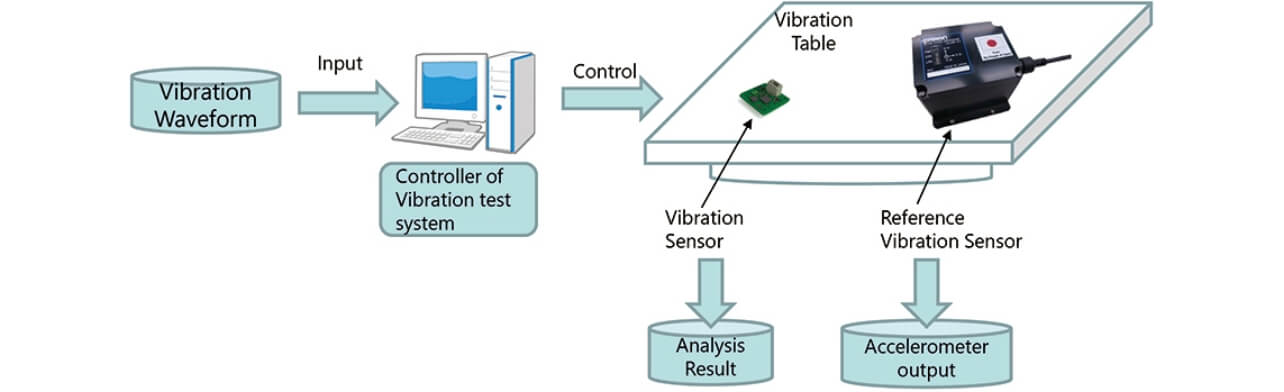
In order to verify that the earthquake waveform entered into the vibration test equipment system was accurately represented in the vibration test equipment, the reference accelerometer is installed to monitor the acceleration.
3.2 Task of verification by vibration test equipment
The vibration test equipment verification has mainly two tasks. First, a determination is made as to whether waveforms such as the earthquake waveform and daily environmental vibration can be accurately reproduced. The earthquake waveform is generally unpredictable, the verification by the actual earthquake waveform is regarded as more important than that by the theoretical waveform, and the verification by many waveforms is required. The period and the amplitude of an earthquake vary depending on the direct type and the plate type, and the magnitude of an earthquake is as wide as the seismic intensity range of 3 to 7. In addition, when verifying daily environmental vibrations, the waveform is more complicated because the instant pulse element is added to the periodic waveform in the case of door opening/closing, fall the heavy loads to floor, vibrations from vehicles, and other vibrations. As mentioned above, the vibration to be reproduced by the vibration test equipment includes many different elements. Therefore, it is necessary to study the reproducibility of the earthquake and the vibration waveform in the allowable actuation range of the vibration test equipment in advance.
The second task is the method for installing a vibration sensor to be verified. The effect of the installation should be excluded because an installation matching the actual use and sufficient vibrations are the major premise.
For the above reason, the exact establishment of a test environment is very important for the accuracy of verification. Therefore, verification using the vibration test equipment in which the establishment of the test environment, the preliminary study, and the review of the results take time and offers very low cost-effectiveness. However, when conducting tests in the environment considering the effect of the inclination of a mounted acceleration sensor and the installation position of the user, the verification using the vibration test equipment closer to the actual state is regarded as important. Therefore, a technique capable of efficient verification is required while minimizing the implementation of a verification using the vibration test equipment.
3.3 Verification method by model simulation
The means for modeling the operation the same as that of a vibration sensor inside a computer and performing the simulation can be considered as the means for optimizing the verification method using a vibration test equipment as afore-mentioned. The calculation of SI values inside the vibration sensor, the modeling of the earthquake determination algorithm, and the utilization of a computer can perform the verification of the calculation and algorithm by exactly reproducing the vibrations without being affected by the test environment, such as the vibration test equipment. However, since the simulator of vibration sensors is not commercialized, a multipurpose numerical analysis simulator will be used.
3.4 Task of verification by model simulation
When using a multipurpose numerical analysis simulator, there is a task where the mutual conversion between the algorithm established by the simulator and the actual embedded software6) cannot be performed.
There are two corresponding methods as measures for this task. The first is a technique for developing an algorithm on the simulator and directly using the code produced using an automatic conversion function7) as the program for the real machine. The automatic conversion function automatically converts the simulation program to the embedded program. In this case, there are problems wherein the error of the calculation result is not guaranteed, the processing time is not considered, and the program size is enlarged. A problem wherein the product cost increases also arises because a change in the MCU is required when the program size is enlarged and the processing speed is insufficient. In addition, since MCU power management, the detailed control of the accelerometer, and the coordinated actions with it are performed in order to achieve low power consumption in the vibration sensor, the reproduction of these functions on the simulator is difficult, and even if reproduction were possible, they could not be adopted because the automatic conversion that includes them encourages the enlargement of the program size, and the problem of the afore-mentioned cost arises.
The second corresponding method is a technique for establishing the product software by manual conversion after establishing and verifying the calculation by the simulator. In this case, it is necessary to manually convert each procedure one by one and to study and convert every time when changing the algorithm. Therefore, the work takes much time, resulting in the generation of the factor rising product cost. Furthermore, since human error possibly enters during the conversion, verification is required as to whether the embedded software and the action on the simulator completely coincide. Thus, repetitive experiments using the vibration test equipment are required even if a simulation is introduced.
Since cost effectiveness is not obtained from the conventional simulation establishment like this, we developed the software by which simulation can be implemented without changing the embedded program.
4. Verification of vibration sensor using reproduction software
4.1 Overall structure
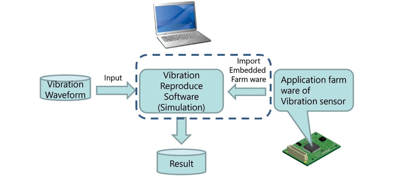
The overall structure of the reproduction software proposed this time is shown in Fig. 5. The simulation will be implemented by preparing earthquake waveforms similarly to the vibration test equipment experiment for entry in the reproduction software that incorporated the vibration sensor program. The reproduction software calculates the SI values on the incorporated vibration sensor program and outputs them.
4.2 Method for realizing reproduction software
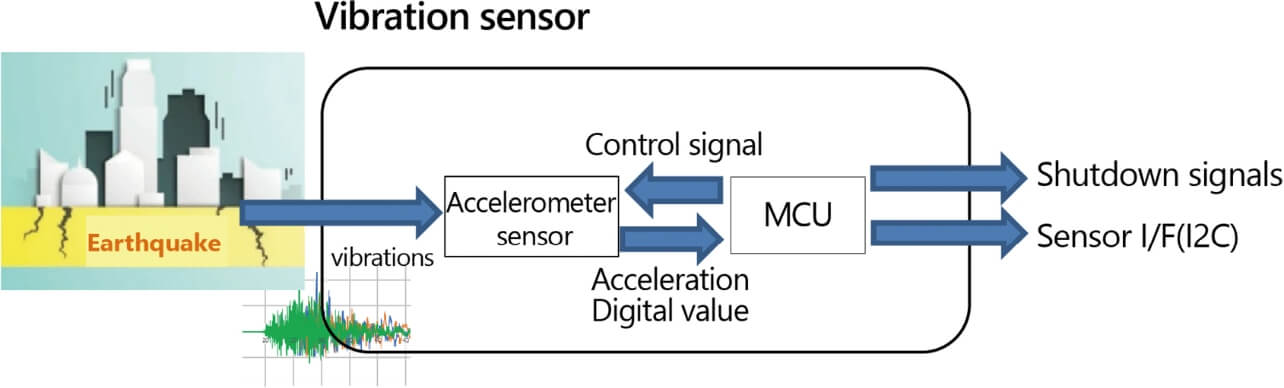
The vibration sensor consists of the accelerometer for detecting vibrations and the MCU for performing the earthquake operation as shown in Fig. 6. The vibration sensor incorporates the acceleration acquired by the accelerometer in the sensor through the SPI communication and processes the earthquake accuracy by the embedded program of the MCU. The embedded program has various elements and is required to reproduce the communication interface function with the accelerometer in addition to the calculation function necessary for the vibration verification. Furthermore, the behavior of the accelerometer must be reproduced. We established these as a virtual accelerometer and a virtual MCU on a computer and established the environment where the whole vibration sensor can be simulated first in the industry.
In addition, the accelerometer of the actual vibration sensor and MCU act in coordination. In order to reproduce this coordinated action on a PC, the thread function performing asynchronous processing is utilized. The MCU and the accelerometer were realized as different threads and made to act asynchronously to assume them as independent behaviors. The interface part among the MCU and the accelerometer became asynchronous communication similar to an actual digital circuit by expressing as an inter-thread communication, and the action similar to real communication action was reproduced. These measures realized a feasible mechanism on a PC without changing the upper layer application part.
4.3 Virtual accelerometer
It is necessary to reproduce the mechanism for detecting vibrations by an accelerometer on a computer for the preparation of reproduction software. For this, the reproduction of three motions is required as shown in Fig. 7.
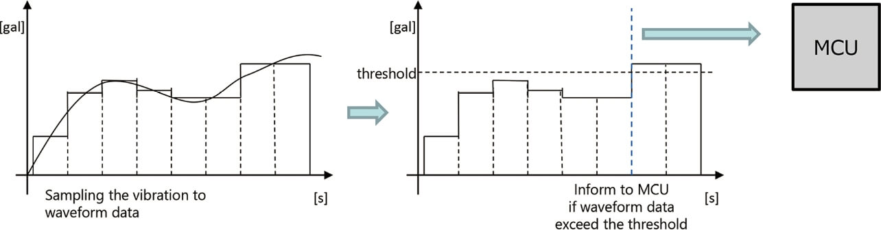
The first motion is where the acceleration sensor continuously performs sampling of vibrations. The second motion is where the vibration is converted into the output of the accelerometer by simulating the digital circuit of the accelerometer. The third motion is that the MCU is started after the accelerometer detect vibrations in a certain level or more. Creation of the virtual accelerometer that transmits these three motions in the same form and timing as an actual accelerometer is necessary.
4.4 Virtual MCU
Fig. 8 shows the comparison of the structure of the actual vibration sensor and the reproduction software. The program consists of the application part for operating the vibration calculation and the vibration sensor described by the upper layer program language, the middleware part that includes the interface function for calculation assistance, and external input/output described by the intermediate layer program language and the device driver part described by the lower layer machine language. Emulation technology is sometimes used if the program is never changed when incorporating all of them into a PC. Usually, since a small-size, low power consumption MCU, such as a vibration sensor, and the CPU used for a PC have no interchangeability of machine language, the machine language of the MCU side is analyzed and interpreted in real time by emulation technology using a high power PC to implement it. However, the emulation technology is provided only for a high-end CPU/MCU in the market and is scarcely applied to small-size MCUs. In addition, since 100 or more types of machine languages operations exist even for small MCUs, and the MCU has a different peripheral circuit for each lineup, it is expensive to establish the emulator for each product development cycle.
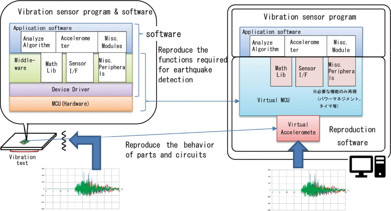
On the other hand, the embedded program language has a form not dependent on the MCU/CPU. Since the upper and intermediate layers are described in the program language, there is a possibility that they can be run as is by a different CPU. In particular, the utilization of the upper layer as is can run the same program on a PC and the MCU. The intermediate layer is used to lower the dependence of the upper layer on the MCU and the peripheral circuits. Therefore, this intermediate layer was changed to realize the behavior of a peripheral circuit of the MCU even if run by a PC when viewed from the upper layer. At that time, the reproduction was limited to the minimum MCU internal circuit, such as the communication function, to the accelerometer necessary for the earthquake detection function of a vibration sensor to create the reproduction software in shorter time in comparison with the establishment of the emulator. In addition, the simultaneous implementation of the calculation and the power management function necessary for lowering the power consumption specific to the product and the utilization was realized without changing the upper layer software, including state transition.
5. Results
5.1 Comparison of earthquake verification results
The results of the magnitude of earthquakes given by the vibration sensor due to the vibration by the vibration test equipment, the results of the magnitude of earthquakes obtained by the simulation by the reproduction software, and the SI value for each magnitude of earthquake are shown in Table 1. The theoretical values are calculated by equation (1). In addition, since the reproduction of the vibration varies, the columns of the verification by the shaking table (old verification) show the average value of ten times. The specification of the SI values of the vibration sensor is ±5 kine and the verification accuracy is sufficient because the error is within ±0.5 kine from the theoretical values, although the error of the earthquake determination algorithm is generated in the reproduction software. However, it is found that the verification accuracy is sufficient since the error is also within ±1.5 kine in case of the verification by the vibration test equipment (old verification).
| Condition | Theoretical value of SI | Verification by vibration test equipment (old verification) |
Verification by reproduction software | ||
|---|---|---|---|---|---|
| SI value | Error from theoretical value | SI value | Error from theoretical value | ||
| Earthquake A | 44.1 | 42.6 | –1.5 | 43.6 | –0.5 |
| Earthquake B | 33.5 | 32.4 | –1.1 | 33.6 | +0.1 |
| Earthquake C | 33.0 | 31.9 | –1.1 | 33.0 | 0.0 |
| Earthquake D | 27.5 | 26.6 | –0.9 | 27.1 | –0.4 |
Furthermore, the daily environmental vibration that was difficult to be reproduced by the vibration test equipment became capable of being easily verified by incorporating the waveform by the reproduction software, and the time for vibration verification was shortened, although repetition was required so far.
5.2 Time required
Experiment time required when conducting using the vibration test equipment:
- Experiment time is approximately 3 min per waveform
- Time for preparing the vibration test equipment system is approximately 5 to 10 min (varies depending on safety check device, etc.)
That is to say, approximately 8 to 13 min are required per waveform.
On the other hand, verification can be performed in approximately 1 min in the case of the reproduction software. Data of more than several ten thousand waveforms are registered in the public earthquake waveform database. It is necessary to perform the verification of earthquakes using several hundred waveforms because the verification is performed based on many patterns. For example, 1,000 waveforms of earthquakes are verified, and the vibration test equipment is required for 10 min×1,000 waveforms=10,000 min/60 min=approximately 167 hours. On the other hand, the reproduction software performs the verification for 1 min per waveform, the time is 1 min×1,000 waveforms=1,000 min=approximately 16.7 hours. As a result, a reduction of approximately 90% is possible.
5.3 Detailed analysis results
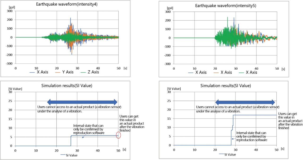
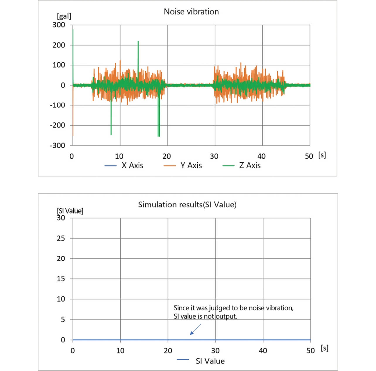
In the verification by the vibration test equipment, the earthquake data stored in the vibration sensor are only checked after the vibrations. On the other hand, the simulation by the reproduction software displayed for each time the earthquake data, such as the SI values, detected by the vibration sensor for vibrations that change every moment as shown in Figs. 9 and 10. This is because the monitoring of the internal data that could not be transmitted due to the sensor that was performing the calculation in the conventional case became possible by reproducing the virtual MCU on the computer program. Since the monitoring of various types of the MCU internal information other than SI values became possible, the analysis and the adjustment of the vibration sensor program could be performed more easily, resulting in the further rise of the development efficiency.
6. Conclusions
Although the exact reproduction and the verification of vibration waveforms of the earthquake waveforms and the daily environmental vibrations using the vibration test equipment or jigs are difficult and take much time, the proposal this time realized reproduction software incorporating the embedded program of the vibration sensor, enabled the verification with accuracy equivalent or greater to the case implemented using the vibration test equipment, and enabled a great reduction in time. In future product development, we will perform the vibration verification, including the various vibration data of which verification could not be implemented due to time constraints.
On the other hand, the functions of the vibration sensor are important not only in the earthquake detection, but also in transmitting and receiving the various data to and from the customers and in the maintenance work. In addition, there are many matters to be verified other than the earthquake verification before the release of the developed product, such as the phenomenon in the case of the simultaneous occurrence of such work and an earthquake and the behavior during a partial failure. Concerning these matters, since the functions other than necessary for the earthquake detection algorithm are omitted from the current reproduction software, the verification is sometimes performed using a conventional system, and some phenomena are difficult to reproduce. We will hereafter develop a technique capable of reproducing and verifying the part other than such a vibration sensing function and develop the vibration sensors with the further higher accuracy and efficiency.
References
- 1)
- Y. Sakai, “Relationship between characteristic of earthquake vibration and damage to buildings,” (in Japanese), J. Jpn. Assoc. Earthq. Eng., no. 9, p. 12, 2009.
- 2)
- OMRON Corporation, “Seismo-sensitive device D7H,” (in Japanese), OMRON Control Equipment. https://www.fa.omron.co.jp/products/family/559/ (accessed Dec. 1, 2020).
- 3)
- OMRON Corporation. “Type D7S Seismo-sensitive sensor,” (in Japanese), OMRON Electronic arts. https://www.omron.co.jp/ecb/product-detail?partNumber=D7S (accessed Dec. 1, 2020).
- 4)
- N. Sato, T. Katayama, N. Okubo, and K. Kawasaki, “Development and trial production of new earthquake sensor for control,” (in Japanese), in The 18th Res. Present. Meet., 1985, pp. 105-108.
- 5)
- S. Hoshi, Y. Maruyama, and F. Yamasaki, “Analysis of relationship between earthquake vibration SI value and damage to wooden buildings based on numerical analysis,” (in Japanese), Paper of Japan Society of Civil Engineers A1 (Structure and Earthquake Engineering), vol. 65, no. 1, 2009, pp. 606-613 (Proc. Earthq. Eng., vol. 30).
- 6)
- T. Fujihiro, Fully understandable basic and mechanism of the latest embedded system, Shuwa System (in Japanese), 2015, 223 p.
- 7)
- Y. Kuroki, M. Tamura, T. Kamiyama, M. Yu, and T. Yokoyama, “Simulink-UML model transformation tool targeting control model including state transition,” (in Japanese), Proc. Inf. Sci. Technol. Forum, vol. 13, no. 1, pp. 193-194, 2014.
Microsoft and Excel are registered trademark or trademark of Microsoft Corporation US in US and other countries.
The names of products in the text may be trademarks of each company.