


Robot Control Program Generation for Cell Production System Based on 3D Simulation
- PLC
- Manufacturing Process Design
- PLM
- 3D Simulation
- Program Generation
In recent years, product lifespans have become shorter because of technological innovation, and it requires manufacturing facility to quickly support new product types. In response to this request, design information of products and manufacturing facilities are comprehensively managed using the Product Lifecycle Management (PLM) information platform, which generate manufacturing work instructions for each product type and issue work instructions to manufacturing workers. On the other hand, the labor shortage is another serious problem, and robotic automation is being attempted at manufacturing sites. Cell production lines run by trained workers can flexibly change the process by changing work instructions. But in the case of equipment automated by robots, it is necessary to change or modify the control programs.
In this paper, we propose a method to generate a robot control program that instructs a robot assembly work cell to execute the assembly process for a specific item by using 3D simulation and the product’s Bill of Material (BOM)/Bill of Process (BOP) information on the PLM information platform. We have obtained a desk calculation result that the man-hours required to modify manufacturing facility to adapt to newly derived items can be reduced by 11% with this method.
1. Introduction
In recent years, technological innovations have caused products to evolve and procurement environments have changed. Because of the resulting factors, such as design changes of parts to be used, product models have become increasingly short-lived simultaneously with increases in derived models. To adapt accordingly, industrial players are strongly required to reduce manufacturing facility start-up periods and achieve faster changeover of the target product type. In response, a product lifecycle management (hereinafter “PLM”) information platform has been introduced to manage the series of processes from product planning to design, development, sales, and disposal, in other words, the life cycle of products in an attempt to provide an integrated management environment for product-variants, bill-of-materials, bill-of-process, and equipment resource information and the like of product models. Proposals for concurrent engineering based on this method have come from PLM information platform providers and others. These proposals aim to perform 3D simulation verification and corrections/improvements of product/manufacturing equipment concepts from the concept phase upstream to the manufacturing engineering chain1). Besides, some PLM information platforms are equipped with functions that work in conjunction with product model-specific work instruction sheet generation and an XR technology-based operator support system. Efforts have been underway to apply such a PLM information platform to flexible work instructions in the cell production system2).
On the other hand, modern manufacturing floors are seriously challenged by labor shortages. Automation has been vigorously pursued to replace manufacturing personnel with robots. In cell production lines with human operators, changes to the manufacturing work process could be made through prior operator training and by making changes to instructions through work instruction sheets. By contrast, automated production lines need changes/modifications of control programs to follow new the manufacturing work processes they provide.
This paper presents our proposed method to configure control programs for use on robotic assembly work cells. It generates control programs to perform assembly work process for a specific product model based on information available on a PLM information platform.
2. Conventional technology and challenges
2.1 Human-operated cell production system
The cell production system is known as a manufacturing system suitable for variable-type, variable-quantity production of products with various derived items3). In this system, units provided with the parts, jigs, and tools necessary for the manufacturing process work around one or a few operators are called cells. This system is employed to implement a cell-by-cell manufacturing process tailored to product work items, thereby facilitating cellular independence maintenance, cell-by-cell layout change, and the increase/decrease of cells per demand to support variable-type, variable-quantity production. Besides, in factories that have introduced a PLM information platform and are equipped with a database compiled from product item-specific bills of materials (BOM) and bills of process (BOP), efforts are made to allow automatic generation of work instruction sheets to cell operators based on PLM information or to enable a quick changeover of the manufacturing item through electronic work instructions using tablets or XR technologies.
2.2 Robotic automation in the cell production system
The conventional cell production system requires training operators into multiskilled operators with a certain level of professional proficiency and, as such, only suits environments with a low turnover of operators. Accordingly, following the recent surge in labor costs and human resource shortages on manufacturing floors, broad efforts are underway to replace operators with robots. Moreover, besides variously sized or shaped industrial-use robots, safety-minded, collaborative robots have started to spread rapidly. In response, robotic assembly applications have been developed that feature impedance control using six-axis force sensors to add high precision to assembly tasks frequently performed on cellular manufacturing lines, such as screwing, fitting, and stickering. These applications have achieved some success4).
2.3 Challenges to robot cells in supporting variable-type, variable-quantity production and accommodating derived items
For a robotically automated cell to support variable-type, variable-quantity production, not only must it perform individual manufacturing tasks, but it requires changing the manufacturing work procedure (process) to suit the manufacturing item or fixing/adjusting control programs to equipment modifications for adapting production to newly derived items. For the conventional cell production system reliant on trained operators, it suffices to prepare manufacturing instructions anew based on the PLM information platform to allow flexible accommodation of derived items. However, a robotically automated cell requires preparing/adjusting control programs corresponding to work instructions and rerunning teaching operations per an in-cell equipment layout or workpiece shape change. A 3D simulator-based offline teaching function is used to reduce manufacturing line downtime caused by teaching operations. However, the desktop work for this purpose also requires a considerable workload.
3. Our proposed method
For the challenge of making a reality a robotically automated cell that flexibly supports variable-type, variable-quantity production and accommodates derived product types, this paper proposes a method that uses the PLM information platform as the source of input to 3D simulations to generate robot control programs as shown in Fig. 1.
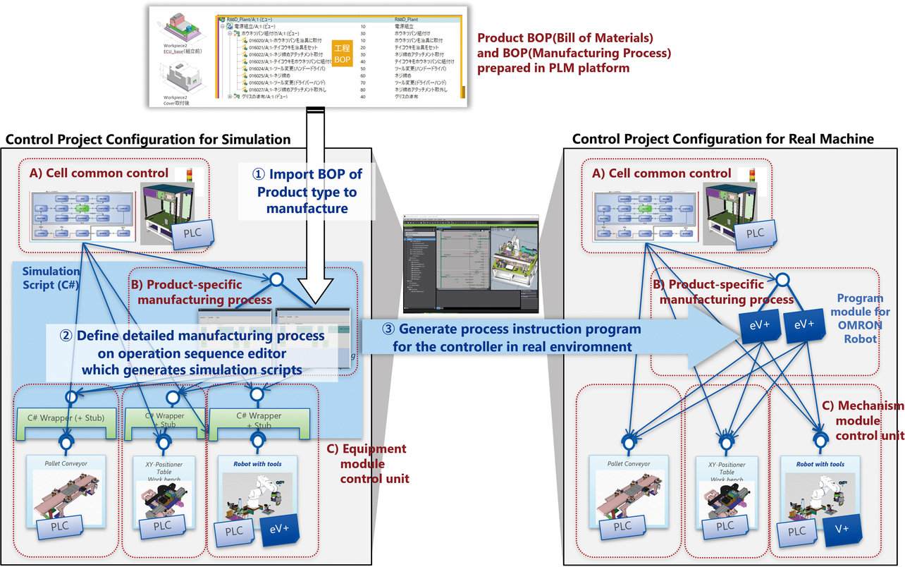
- (1) For a product family to be manufactured, its 3D-CAD, bill-of-materials (BOM) and bill-of-process (BOP) information managed on the PLM information platform is imported to the prototype Task Sequence Editor tentatively implemented on Omron’s FA-integrated development environment, Sysmac Studio.
- (2) Using the Task Sequence Editor, the user defines the details of the manufacturing work process in the robot cell, thereby generating a Shape Script, a C#-based simulation script for running a 3D simulation on Sysmac Studio.
- (3) Through the execution of such a 3D simulation, task target coordinates are obtained from the current position of a 3D shape model of a workpiece, thereby generating an eV+ program module, a program for controlling an actual OMRON-built robot.
We prototyped some of the functions necessary for this method and verified their feasibility and expected effects.
4. Details of the prototype-based feasibility study
4.1 Verification-target equipment and verification scenario
We used the design information of the automatic assembly cell model unit for circuit board modules (hereinafter “robot cell”) shown as the verification target in Figs. 2 and 3:
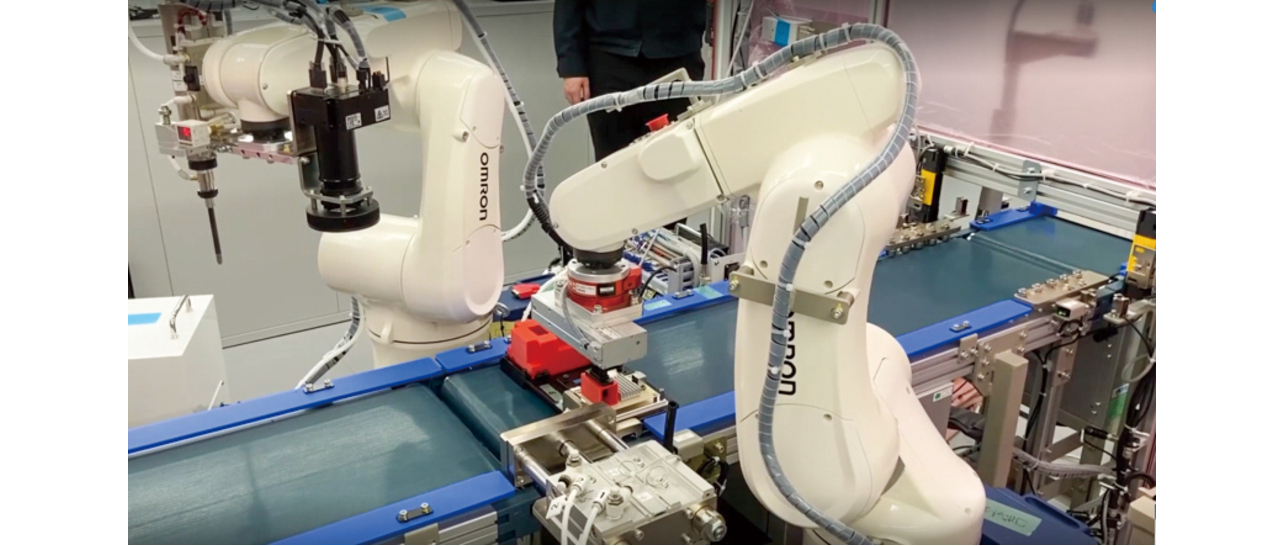
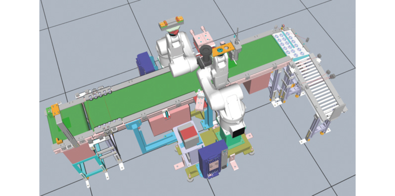
This robot cell was built for the demonstration of Omron’s Robotic Integrated Controller5). It was designed to enable the mixed-flow assembly of multi-item simulated products simulating electronic control board units for automobiles.
Moreover, using a commercially available PLM information platform system6), we prepared and stored in it the 3D-CAD, bill-of-materials (BOM) and bill-of-process (BOP) information for the item family of the simulated products, along with the 3D-CAD and bill-of-equipment-modules (BOE) information of the robot cell. Considering the pre-existing context of the mixed-flow production of two different product items, we assumed a situation where a third derived item occurred, whereby its bill of materials and bill of process were added to the PLM information platform. Fig. 4 outlines the assembly processes for these three items.
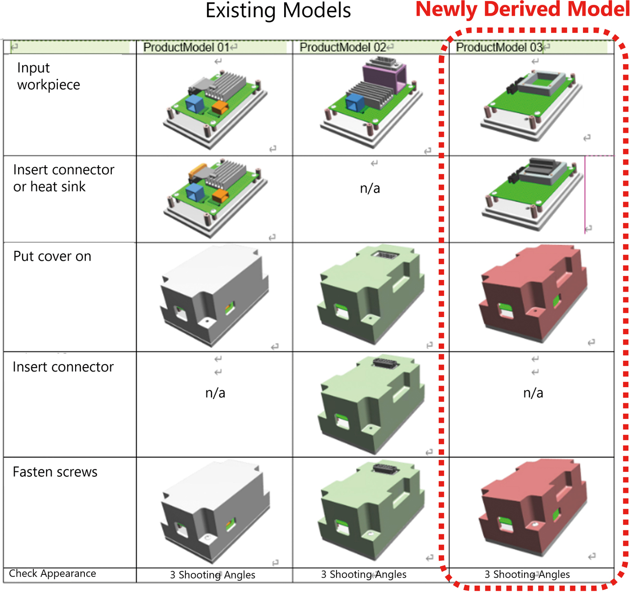
For an equipment modification scenario for including this third derived item in the scope of the mixed-flow production using the robot cell, we estimated the feasibility of our proposed method and the resulting workload reduction effect.
4.2 Internal configuration of the robot cell control programs
For our proposed method to provide effective use, the control program architecture must be creatively designed to allow changeover between the manufacturing work processes to suit the target item. The control program for the robot cell for verification consisted of control duties split in the configuration shown in Fig. 5.
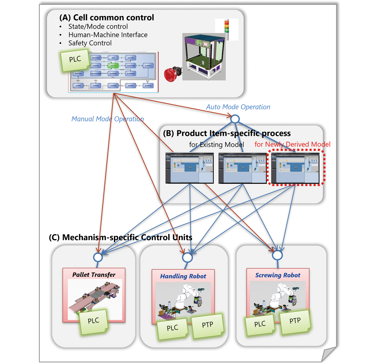
For the Mechanism-Specific Action Control Block in Fig. 5 (C), a motion control program was deployed for each mechanism unit placed inside the cell to achieve a specific function/manufacturing task through the action of the mechanism.
The Product Item-Specific Work Process Block in Fig. 5 (B) was provided to execute sequentially the different function/task execution programs provided by the Mechanism-Specific Action Control Block in Fig. 5 (C) according to the product item-specific assembly work process.
For the Robot Cell-Wide Control Block in Fig. 5 (A), a program was implemented that could provide the following as the behavior/external interface specifications for the cells constituting the line to have in common:
- Controlling the operation mode or state of the cell as a whole
- Interfacing with the host manufacturing execution system (MES) or the upstream/downstream cell
- Safety controls such as safety fence, light curtain, and emergency stop switch
- Common control for human-machine interfaces (HMI), such as the operation panel and a signal tower
- Selecting and running automatic mode-executable programs in the Product Item-Specific Work Process Block in Fig. 5 (B)
- Selecting and running manual mode-executable function/task programs in the Mechanism-Specific Action Control Block in Fig. 5 (C)
We ensured that a process control program for the Product Item-Specific Work Process Block in Fig. 5 (B) was generated and added based on BOP information to accommodate the newly derived product type.
4.3 Preparation of product BOM/BOP information
This subsection describes the BOP information available on the PLM information platform for verifying the generated process control programs. Generally, the PLM information platform is used to manage the bills of models (items) defined for product families to be manufactured and their product item-specific bill-of-materials (BOM) and bill-of-process (BOP) and, depending on the case, bill-of-equipment (BOE) information. In practice, however, though often generalized as BOM or BOP, such information varies in the granularity or degree of detail of information, depending on the factory that operates it. We made available on a commercially available PLM information platform the BOM, BOP, and BOE information structurally organized as shown in Fig. 6.
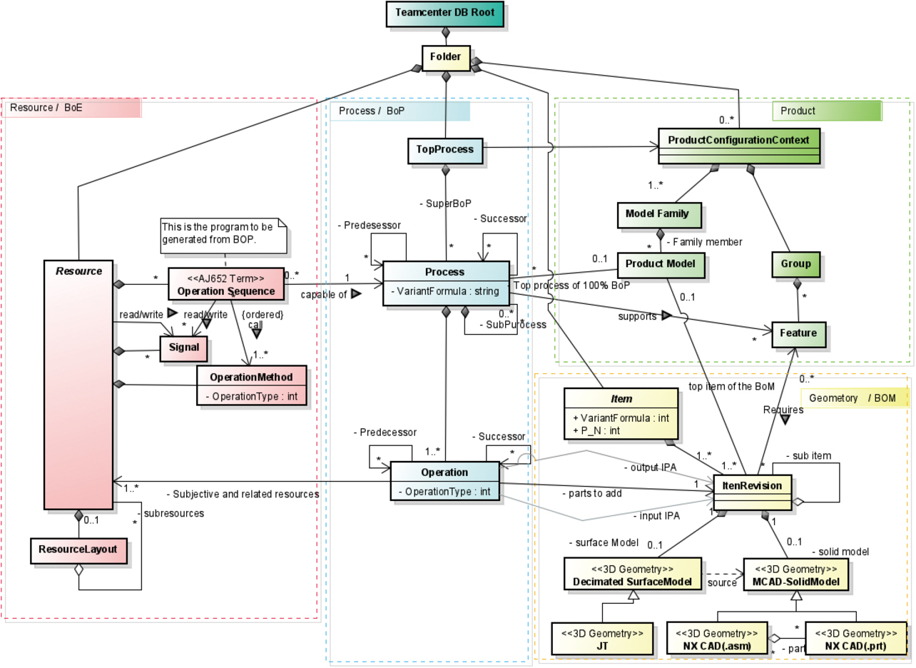
Generally, a BOP associated with a product item defines the lead-and-follow relationship between the tasks constituting the assembly process for the item and how to mount what parts on the in-process workpiece as the input to each assembly task using what manufacturing resources (machine, tool, jig, or operator). The commercially available PLM information platform system used this time comes with a Manufacturing Process Editor7) available to define the chronological order of process operations in PERT chart format.
We configured properties to draw the following information for each process work item to generate a process control program based on the BOP:
- Identifier of the preceding task
- 3D model of the in-process workpiece before the preceding task
- 3D models of additional parts
- 3D model of the in-process workpiece after the preceding task
- Identifier of the following task
4.4 Simulation preparation for the mechanism control unit group
In preparation for running an assembly process simulation based on the BOP information, we first created in advance a 3D mechanism simulation model for the robot cell on Sysmac Studio.
In this way, we arranged for the simulator to reproduce the function/task provided by each mechanism unit shown in the Mechanism-Specific Action Control Block in Fig. 5 (C). The verification-target robot cell consisted of three different mechanism units, a Pallet Transfer Unit, a Handling Robot Unit, and a Screwing Robot Unit, with the function provided by each mechanism unit being configured as in Fig. 7.
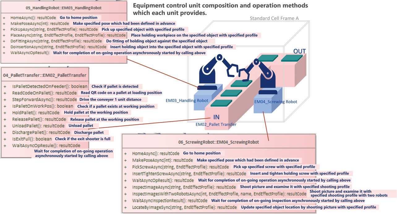
We prepared a Shape Script to run the functions/tasks of the mechanism units shown in Fig. 7 on a Sysmac Studio 3D simulation. Note that the mechanism-unit control program used to operate each real machine would not run normally if no proper response was returned to an input signal from the sensor to the actuator output to the mechanism side. If the mechanism is simple, such as a conveyor, the response can be reproduced on Sysmac Studio. However, no proper reproduction of robotic force control is possible based on an input signal from a six-axis force sensor provided on a robot wrist. For such cases, we implemented a Shape Script not as a real-machine control program but as a stub capable of reproducing a dummy task at a takt time appropriate only on a 3D simulation.
In defining a Shape Script for thus reproducing the function provided by each mechanism unit, we considered and configured the function call interface as follows:
- Configuring as a virtual method the call interface for the function/task provided by each mechanism unit
- The suffix “Async” is added to the name of a virtual method that assumes an asynchronous call for a task executed parallelly with the tasks assigned to the other mechanism units. A WaitOperationResult method common among the mechanism units is defined for each wait for task completion.
- For the same function/task, a work target can be specified using a parameter (value passed at the run-time). For work-target specification, the distinguished name of a 3D simulation object is used rather than coordinate values.
- Details such as a work target’s approach direction or distance to a 3D object can be predefined as parameters in the information explained later and known as end-effect profiles.
Table 1 shows the virtual methods for the simulation prepared for the Handling Robot Unit shown as 05_HandlingRobot in Fig. 7, along with examples of their corresponding parameter configurations:
| Virtual method | Parameter configuration |
|---|---|
| HomeAsync Starts traveling to the home position. |
― N/A |
| MakePoseAsync Starts traveling to the specified pose. |
1. poseIndex: int Pose index |
| PickUpAsync Starts the pick-up of the specified workpiece |
1. workpieceName: string Grip-target 3D object name 2. graspProfile: End-effectProfile Grip-profile object |
| PlaceAsync Starts placing the gripped workpiece on the specified object. |
1. placeProfile: End-effectProfile Profile object used for Gripped Workpiece Placing action 2. releaseProfile: End-effectProfile Profile object used for Post-Placement Hand Release action |
| DoFittingAsync Starts locating the fitting position of the gripped workpiece into the specified object. |
1. tagetObjName: string Target 3D object name 2. fittingProfile: End-effectProfile Profile object for Fitting-Position Locating action |
| DoInsertionAsync Starts the profile insertion of the gripped workpiece. |
3. tagetObjName: string Target 3D object name 4. intertProfile: End-effectProfile Profile object for Insertion action |
| WaitOperationResult Waits for the completion of the task started shortly before in order to obtain the result. |
― N/A |
Similarly, for the Pallet Transfer Unit and Screwing Robot shown in 04_PalletTransfer and 06_ScrewingRobot in Fig. 7, we prepared simulation scripts for virtual methods corresponding to their functional configurations. These arrangements provided the ability to define the call sequence for the function provided by each mechanism unit as Product Item-Specific Work Process Block in Fig. 5 (B) while passing as parameters the 3D work object names of in-process workpieces or mounting parts contained in the product BOP information loaded into Sysmac Studio. Thus, we created an environment for running 3D equipment simulations capable of reproducing the assembly process required by the product BOP.
4.5 Description of the product item-specific assembly work process
Based on the abovementioned BOP information, this subsection explains the method that generates Shape Scripts to run assembly process simulations using the Sysmac Studio 3D simulation function.
The commercially available PLM information platform system used this time can export selected optional information in XML file format8). The XML schema specification is publicly available for free. No technical challenges have been identified in this respect. Hence, assuming that BOP information prepared beforehand was exported and successfully imported into Sysmac Studio, we excluded from the efforts presented herein the prototyping of the function to import this information.
The product BOP imported from the PLM information platform contains assembly work requirements from the product point of view, such as how to mount what shape parts on the in-process workpiece. However, it stops short of detailing the procedure for implementing the requirements through the equipment function. The assumption herein is that the user is allowed to define the assembly task sequences to call the various functions/tasks provided by the mechanism units to satisfy the work requirements contained in the imported product BOP information. We prototyped a Task Sequence Editor for this purpose. Actions performed on the Task Sequence Editor include the following: loading in-process workpieces; feeding and receiving parts to be mounted thereto; unloading finished workpieces; waiting for completion between parallel tasks; and specifying state transitions at anomaly detection during individual tasks. Assuming use in a typical robotic assembly cell, we considered the logic control elements necessary therefor and, as a result, identified the following six types:
- A) Synchronous call processing
- Used for sequential processing of tasks arranged in normal order.
- B) Asynchronous call and wait for completion
- Used to describe interlocks during parallel processes/tasks. Required when multiple actors, such as robots, are laid out in the same cell and operate without synchronization.
- C) Conditional branching and iterative processing
- Used to describe the same screwing task performed at multiple points or minor troubleshooting through automatic resumption and continuation.
- D) Subroutinization and calling of sequence processing
- Necessary to structurize processing, especially to configure and call the various functions provided by the mechanism units.
- E) Exceptional error catching
- Non-mandatory but useful for error handling if available.
- F) Interruption and resumption of sequences
- Used to instruct a resumption of an interrupted task after an interruption due to a serious error and manual recovery by the operator.
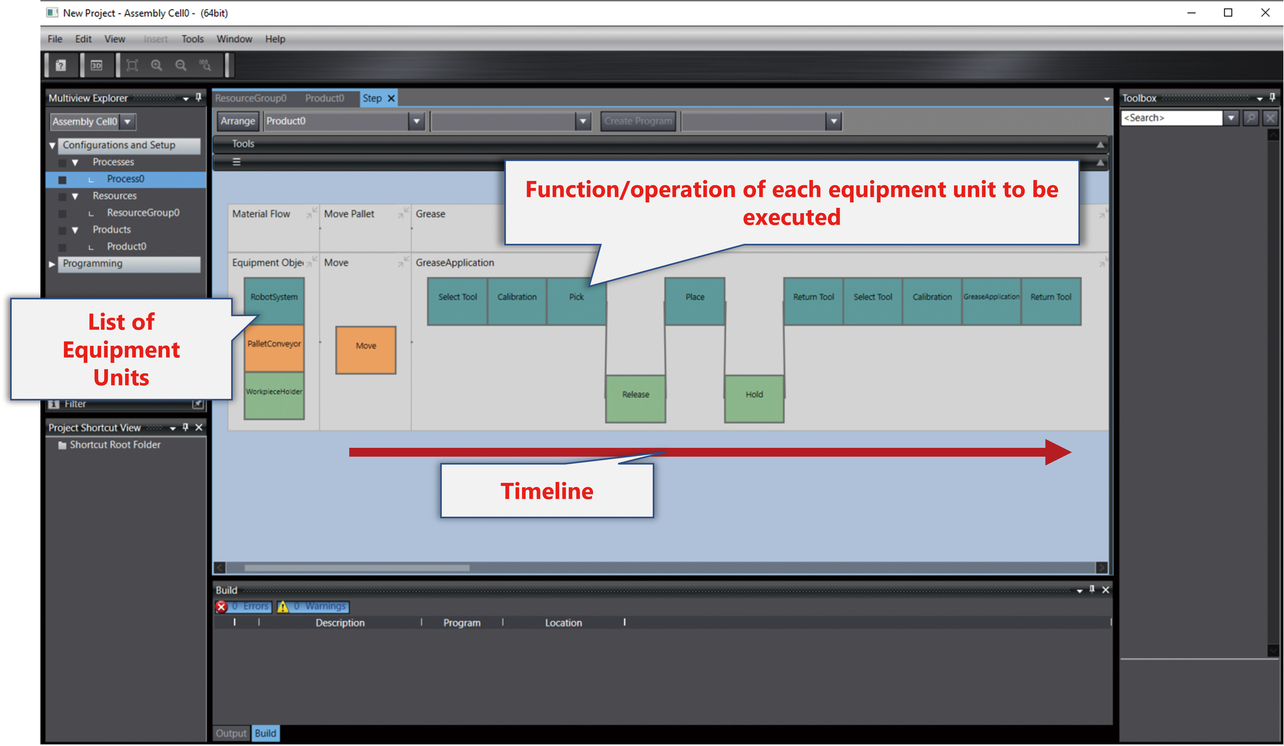
Then, we considered a specification plan for the Task Sequence Editor’s operation screen (Graphical User Interface: GUI). Fig. 8 shows the timing chart-like GUI plan for our prototype.
4.6 Definition of end-effect profiles
The Task Sequence Editor presented above allows the user to specify individual mounting task types, including screw pick-up, screwing, fitting, and profile insertion, the 3D object types of the target workpiece and parts, and even the order of tasks. However, more information is necessary to operate actual robots. In the case of the workpiece pick-up task, for instance, a detailed positional relationship between the gripper and target object and action command issues to the gripper must be specified, such as what path in what direction the robot wrist-mountable gripper should follow to approach the target workpiece/part, at what point in what direction the gripper should close, and in which direction the gripped workpiece/part should be lifted.
For detailed specifications of the end-effector tasks performed on the target object using end-effectors, such as a robot wrist-mountable gripper and an electric screwdriver, we prototyped an editor shown in Fig. 9. This editor generates distinguished names to save end-effect profiles, pieces of information specified using the Shape-Script type names and instance names of 3D objects/work targets.
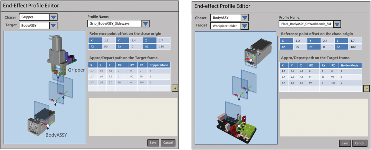
An end-effect profile consists of the following information:
- Profile identifier: An ID that uniquely identifies the end-effect profile concerned in the project.
- Profile view name: A self-evident name transparent to the user, such as the following:
- Grip_BodyASSY_sideways_by_Gripper_A
- Place_BodyASSY_ sideways _on_pallet
- Overlay_BodyASSY_on_HeadASSY
- Slave 3D object’s type name: The type name of a mover-side 3D object, such as Gripper_A, for example.
- Master 3D object’s type name: The type name of a targeted-side 3D object, such as BodyASSY, for example.
- Ordered list of [relative position, relative pose, and relative moving speed] of the slave 3D object with the local coordinate system of the master 3D object as the reference coordinate system.
- Command value to peripheral equipment to be executed per element (relative position/pose) in the above list, such as a Grip/Release action command output to the gripper or a wait for a gripping completion input from the gripper.
This end-effect profile is used as a parameter to enable each mechanism unit to execute the function/task method they provide. As a result, it became unnecessary to define similar detailed actions of the robot and end-effector over and over again for similar screwing tasks at multiple points on a workpiece or the grip or release action for transferring an identical 3D-shaped workpiece on a different point.
4.7 Simulation execution and process control program generation
Fig. 10 shows the overall view of generating the process control programs corresponding to the Product Item-Specific Work Process Block in Fig. 5 (B), based on the manufacturing item-specific BOP information managed on the PLM information platform.
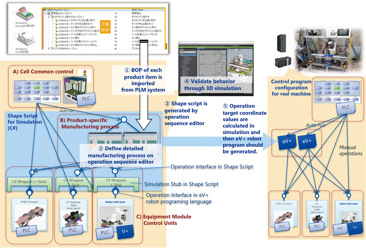
Of Steps (1) to (5) in Fig. 10, the preceding subsections described Step (1) in which the Task Sequence Editor imports the BOP information from the PLM information platform, and Step (2) in which the equipment developer defines the details of the work process contained in the BOP, using the Task Sequence Editor. This subsection explains Step (3) in which the Task Sequence Editor generates a Shape Script for a simulation; Step (4) in which the equipment developer uses it to perform an operation verification on a 3D simulation; and Step (5) in which the simulation script generates process control eV+ programs.
In Step (3) in Fig. 10, a Shape Script is generated based on the information defined using our prototyped Task Sequence Editor and End-effect Profile Editor. At this step, the Shape Script generates a logic framework whereby the logic of the task sequence defined by the editor can be reproduced upon running the simulation.
At the same time, we prototyped a C# generation code embedded in the Shape Script logic framework, whereby eV+ program text would be generated for calling each mechanism unit’s task method to reproduce the order of tasks and the wait condition deployed through the execution of the logic. The task method provided by each mechanism unit was implemented here using eV+ for real-machine control, thereby requiring that the task target be specified using eV+ location variables (six-degrees-of-freedom coordinate values in the robot coordinate system concerned). Accordingly, a query was sent to the simulation engine to obtain the current position information of the work-target 3D object specified by the Task Sequence Editor, thereby converting the relative position information of the work-target 3D object type and the robot hand position predefined by the End-effect Profile Editor into absolute coordinate values in the robot coordinate system concerned. A Shape Script was generated to generate an eV+ program to give these values to the task method of each mechanism unit.
These arrangements enabled the following: when 3D simulation verification is performed of the work process for a product item at Step (4) in Fig. 10, an eV+ program code is dynamically generated at the execution of the Shape Script based on the current position information on the 3D object and sent to the robot simulation engine, whereby the equipment operation simulation behavior is reproduced, including the robots; then, in the final process of the Shape Script, the eV+ program code group used to run the 3D simulation is compiled into an eV+ program module that represents the task sequence and is added to the Sysmac Studio project as in Step (5) in Fig. 10.
The above observations confirmed that an eV+ robot program module for issuing work process instructions to the mechanism units based on each task target’s coordinate values can be generated by running a 3D simulation that reproduces a series of assembly work processes based on details defined using the Task Sequence Editor and the End-effect Profile Editor.
5. Estimation results for workload reduction effect
To estimate the effectiveness of our prototyped functions, we assumed a scenario of modifying the two-product assembly robot cell presented in the previous section to accommodate the newly derived third item. In this scenario, the newly derived item product used a screw of a different size than for the existing item. Hence, the assumed scenario included an in-cell equipment layout change for laterally shifting the position of the screw feeder for the existing product items to obtain a space to install an additional screw feeder for the derived item.
Changing the equipment layout inside the robot cell would affect the manufacturing of both new and existing items. Therefore, a system concept aimed at equipment modification must verify the manufacturing workability and takt time of the assembly process for all manufacturing items, including both existing and new items, for each equipment layout plan. Existing 3D simulation methods require repeating numerous offline teaching operations and program fixes many times until an adequate equipment layout plan is obtained. Our prototyped process control program generation function serves as a method to perform 3D simulation verification of item-specific assembly processes without needing any script fixes or offline teaching operations. This achievement enables the speedy development of a system concept aimed at equipment modification planning. Besides, process control programs for real-machine operation are generated by reducing the software production workload.
Fig. 11 shows the results of performing a desktop estimation of the workload reduction effect achieved using our prototyped functions according to the scenario presented above based on the development workload data for a similar robot cell built to estimate the workload reduction effect in the development of the Robotic Integrated Controller. While Case (A) in Fig. 11 involved no equipment simulation environment, Case (B) in Fig. 11 involved an equipment simulation. In Case (B), as opposed to Case (A), the simulation verification in the system concept allowed front-loading of problems, leading to expectations for significant reductions in production/real-machine tests and on-site adjustments.
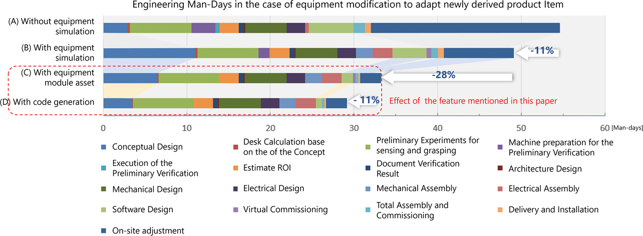
However, an increased simulation preparation workload suggests that the overall workload reduction remained around 11% (4.5 man-days). As opposed to Case (B) in Fig. 11, Case (C) assumed, besides the use of an equipment simulation environment, an equipment design on a modular basis in conjunction with the design assets of the mechanism unit shown as an example in Fig. 7. The assumption was that when newly designed, the equipment was modularly designed to reuse pre-developed simulation models of mechanism units and field-proven control programs. As a result, the system concept development and software production workloads were reduced successfully, thereby solving the technical challenges in function implementation on a per-mechanism unit basis. Consequently, fewer problems were encountered during the real-machine test and the on-site adjustment phase, promising an overall workload reduction of 28% (16.5 man-days). For Case (D) in Fig. 11, to which the technology presented herein was additionally applied, a simulation script and robot control program were generated based on the BOP information of the derived item, resulting in a prospect of further reducing the system concept development and software production workloads with an additional overall workload reduction of 11% (4.5 man-days).
6. Conclusions
Our efforts presented herein aimed to accommodate derived items flexibly in automated equipment and prototyped a support function that allows the user to define an assembly task sequence for each item on the robotic assembly work cell based on the BOM/BOP information made available on the PLM information platform to show product variations. We devised a series of methods that perform the following: generating a script for running a 3D simulation of the assembly work and running the script to calculate the task target coordinate values based on the shape and position information of the 3D workpiece model, thereby generating robot control programs for real machines. We verified the feasibility of these methods using functional prototyping. Besides, the support function mentioned above eliminated the need for offline teaching operations, automating the preliminary simulation verification of equipment layout changes due to equipment modifications and the modification work on real-machine control programs. The resulting estimate was an 11% reduction in the overall equipment modification workload required to accommodate a newly derived item.
The practical application of our proposed method requires that the robot cell itself consist of a mechanism unit group equipped with functions/task methods necessary for multi-item manufacturing work, as shown in Fig. 5 or 8. Reasonably extensive design knowledge is necessary to convert the design of such mechanism units into a digital design asset as an engineering method of implementing a manufacturing work process and for use in equipment design on a modular basis. However, such an achievement would further reduce the task workload, as shown in (B) in Fig. 11. Then, to achieve workload reduction by converting such an engineering method into a digital asset for use in modular equipment design, we will move ahead with identifying applicable equipment domains with promising cost-effectiveness prospects and acquiring necessary technologies.
Acknowledgments
This paper is a summary of some of the outcomes of our technology development project implemented from 2021 to 2023. The author would like to sincerely thank his project team colleagues, namely, Mr. Kenichiro Mori, Mr. Tetsuro Sugihara, Mr. Ramon Latorre, Mr. Ian Mcardle, Mr. Mark Tammadge, and Mr. Stephen Blake, for their diligent efforts in this technology development project. The author would also like to express his deep gratitude to Mr. Yuki Uchiyama for providing the design information of the robot cell presented as the verification target in this paper.
References
- 1)
- M. Kashiwagi, “PLM and Growth Strategies (No. 4) Development Period Reduction - Development Process Redesign and Concurrent Engineering,” (in Japanese), Mach. Des., vol. 51, pp. 100-103, 2007.
- 2)
- PTC Japan. “Manufacturing Industry DX Through PLM Solution “Windchill” - What Future Lies Ahead of Improved Product Quality, Reduced Cost, and Higher Operational Efficiency?” (in Japanese), TECH+, https://news.mynavi.jp/techplus/kikaku/20230929-2779239/ (Accessed: Oct. 1, 2023).
- 3)
- H. Iwamuro, Cell Production System, (in Japanese), Nikkan Kogyo Shimbun, 2002.
- 4)
- S. Ando et al., “Automatic Damping Tuning of Impedance Control for Assembly Task,” (in Japanese), J. Robot. Soc. Jpn, vol. 29, no. 7, pp. 564-572, 2011.
- 5)
- OMRON Corporation. “Robot Integrated System.” (in Japanese), Product Lineup. https://www.fa.omron.co.jp/product/robotics/lineup/integratedcontroller/ (Accessed: Feb. 20, 2024).
- 6)
- SIEMENS. “Teamcenter PLM software.” Teamcenter. https://plm.sw.siemens.com/ja-JP/teamcenter/ (Accessed: Feb. 20, 2024).
- 7)
- ERP Information. “Manufacturing and material data management.” Siemens Teamcenter (Modules, Benefits, and Limits). https://www.erp-information.com/siemens-teamcenter (Accessed: Feb. 20, 2024).
- 8)
- SIEMENS. “PLM XML.” PLM Components. https://www.plm.automation.siemens.com/global/ja/products/plm-components/plm-xml.html (Accessed: Feb. 20, 2024).
The names of products in the text may be trademarks of each company.