


Efficient Specification Improvement of a System Used Globally by Utilization of Information Architecture Modeling
- Information System
- Knowledge Management
- Information Architecture
- System Architecture
In OMRON’s factory automation business, we provide solutions to address customer manufacturing issues by combining a rich product lineup and control algorithms. To expand this solution horizontally, we have built a technological knowledge sharing system and have made small improvements through DevOps, a collaborative effort between development and operation, but we are redeveloping it to improve the efficiency of technological knowledge use. How can we derive system specifications that balance various elements such as business goals, laws and regulations, and data quality while listening to the voices of users? How should we reach agreement globally? The solution is information architecture modeling. We identified six models that can express the intent of formulating system specifications in a simple, bird’s-eye view, in a multifaceted manner, and modeled the concept of a new system that improves operability by about 30% and improves chained knowledge references. Using the model, we lowered the language and knowledge hurdles of the stakeholders, established a common understanding of the concept, and then formulated and agreed on the system specifications.
1. Introduction
Solutions to challenges at customers’ manufacturing sites require utilization technologies based on algorithms, products, or combinations of products that use control, motion, image processing, AI, robotics, and other advanced technologies. We can improve solution delivery quality and efficiency by turning these utilization technologies into knowledge for sharing among engineers deployed at global bases to prevent duplicated developments and obtain extensive findings1).
We developed a global technological knowledge-sharing system for accumulating and sharing such technological knowledge. When initially released, this system supported only the minimum required functions. Later, the system underwent minor modifications through DevOps. The numbers of both technological knowledge registrations and references are on the increase.
We planned a large-scale system modification for further efficient technological knowledge sharing1). We interviewed users and operating departments to identify challenges to efficient utilization and to develop the specifications for a new system that could solve them. To determine the system specifications, we needed coordination with users representing individual global bases (hereinafter “base representative users”). However, such a process tends to fall into arguments for partial optimization due to language differences and knowledge gaps, making it hard to reach an agreement. To avoid this problem, we used an information architecture modeling technology. Information architecture modeling served as our method of representing the current system’s analysis and the new system’s concept. We created and used models to establish a shared understanding with the base representative users to bring the system specifications into overall optimal alignment.
2. Challenges
We interviewed the users and operating departments to collect diverse requests. Then, we screened out requests that could not be solved by measures localized to specific screens or logic. This paper discusses two challenges summarized from the perspective of utilization efficiency.
2.1 Challenge (1): Frequent cross-screen operations
Our system uses SharePoint Online. From the perspective of intellectual property rights protection and export control, we developed an independent site for each global base. Each site has a library configured per type of technological knowledge. Moreover, a home site exists that controls the entire system as a whole.
Our system makes combined use of the screens equipped standard to operate the libraries provided by SharePoint Online (hereinafter “standard screen”) and custom-developed screens based on the SharePoint Framework (hereinafter “custom screens”). The standard screens can be described as helpful in reducing development costs but not easy to interface with other sites, whereas custom screens can be characterized as easy to interface with other sites but likely to increase development costs. The standard and custom screens are implemented in base-specific sites and the home site.
This large number of screens requires cross-screen operations, reducing the users’ operation efficiency.
2.2 Challenge (2): Weak relationships between accumulated technological knowledge
Systematic registration of technological knowledge enables chain referencing, for the purpose of which technological knowledge is associated with each other. However, such associations cannot be made freely but must be made according to some rules. For example, technological knowledge falling under the technological knowledge type “Applications” can be associated with those falling under the technological knowledge type “Success Stories.” However, many cases are known of incorrectly associated accumulated technological knowledge. The technological knowledge thus accumulated non-systematically cannot be shared effectively or utilized efficiently by users.
3. Solution
We turned our eyes to information architecture methodology to perform analysis and concept design for developing a system easily understandable by stakeholders.
3.1 Information architecture
Based on the references listed at the end2,3), this paper represents the information architecture as follows:
- The information architecture is the structure of information intrinsic to the system.
- The information architecture represents the intent of developing the system specifications.
- The information architecture varies depending on the system.
Table 1 lists the elements required for the information architecture. These elements are interdependent. It is essential to build an information architecture with these elements well-balanced, regardless of what priorities or constraints should be added, depending on the target system.
| Category | Elements included in each category |
|---|---|
| Context | Business goals, funding, laws and regulations, politics, culture, core competencies, technologies, resources, etc. |
| User | Needs, tasks, information search behaviors, experiences, etc. |
| Content | Data, data types, metadata, existing structures, etc. |
3.2 Information architecture modeling
“Information architecture modeling” means representing an information architecture as a straightforward, bird’s-eye-view, and multi-faceted model. Useful views of stakeholders can be fed back to the model. At the same time, the model can serve as an explanation against views biased to specific elements. The model enables establishing a shared understanding with stakeholders.
3.2.1 Approach
We took an approach based on the concepts of existing physical, existing logical, future logical, and future physical models used in the structured analysis4). Fig. 1 shows this approach.
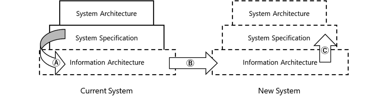
Let us assume that, at present, there is no representation of the information architecture of the current system. Then, (A) its intrinsic information architecture is reverse modeled from the system specifications, followed by (B) modeling the information architecture of the new system so that it can be compared with the current system and (C) establishing the new system’s specifications based on the modeled information architecture.
Before aligning our system specifications with the base representative users, we established a shared understanding using the information architecture representing the intent of developing the specifications. Assuming that the information architecture would be challenging for the base representative users to understand, we took an approach that would help them understand it based on models for the current system’s specifications already familiar to them so that they could compare the current and new systems.
3.2.2 Identification of models
Site map and wireframe models may serve as examples of typical types of models. However, no standardized rules exist for the types and notations of models to be represented. Moreover, the information architecture varies depending on the target system because of the differences between the elements shown in Table 1; hence, the type and notation of the model must be identified for each target system.
For our system, we first performed an analysis from the perspective of the elements listed in Table 1. We analyzed logs for tasks or information search behaviors and then accumulated data for data or existing structures, business innovations for business goals, and interview results for needs or experiences, among other things, to create deliverables. In addition, we also created area divisions for screen redesign, a list of standardized definitions and terminology, and other various deliverables. While these deliverables could all be turned into models, we considered whether excessive modeling or disclosure would prevent the new system from being understood by the base representative users of the current system already in operation. Then, we identified six different models created on the basis of these deliverables as the model types to be represented for our system. Table 2 shows these models with their notations included:
| Designation | Description | Notations |
|---|---|---|
| Knowledge relation map | For technological knowledge forming the core of the data handled by the system, this model comprehensively represents the types and relations of such technological knowledge. | Represented as a UML class diagram (package = technological knowledge category; class = technological knowledge type; association = that between technological knowledge types). |
| Tag structure diagram | For technological knowledge tags necessary for filtering, including searching, this model comprehensively represents the types and relations of such tags. | Represented as a UML class diagram (class = tag type and technological knowledge type; association = that between technological knowledge type and tag type). |
| Layout | This model comprehensively represents the layout of technological knowledge and screens/logics. | Represented as a UML layout (node = home site/base site; component = screen/logic; artifact = technological knowledge type). |
| Static site map | This model comprehensively represents the relations between screens/menus and transitions. | Represented as a UML class diagram (package = screen/menu category; class = screen/menu; association = transition). |
| Wireframe | This model represents images of representative screens that appear on a static site map. | Each screen is divided into areas, each with a simplified image representing a UI part placed in it. |
| Dynamic site map | This model uses representative scenarios to represent operations on a static site map. This model is used to simulate operations. | Besides scenario textual expressions, this model uses arrows, numbers, and the like to represent operations or screen transitions for satisfying the scenario on a static site map. |
Technological knowledge types and their relations were represented in knowledge relation maps, while tags assigned to technological knowledge were represented in tag structure diagrams. It is a system constraint to configure independent sites base by base from the perspective of intellectual property rights protection and export control. Hence, we represented these sites in layouts accordingly. Screens and transitions were represented on static site maps, while individual screen structures were represented in wireframes. Simulations based on representative scenarios were represented on dynamic site maps.
3.2.3 Notes for modeling
Assuming video meetings, we represented each model in a bird’s-eye view to check it on a PC display screen for discussion. Moreover, we ensured that anything unchanged between the models retained the same size and position for easier comparison before and after changes.
The textual expressions on each model were all in plain English so that the models could be standardized globally. It is particularly important for any model that all the target data be modeled without discrepancies or inconsistencies. We rendered complicated models, even those containing many association lines, for example, easily understandably by ingeniously positioning or color-coding their elements without omitting them. However, when we found any model representation too redundant to be understood depending on the intended persons, we made a simplified version available separately, assuming it was free of discrepancies or inconsistencies.
3.2.4 Results of modeling
For the current system, we modeled it as was through analysis. Ambiguities likely to be noticed when visualized were reanalyzed before representation. Meanwhile, for the new system, we created models that would solve the challenges, bearing in mind the balance among the elements in Table 1.
The rest of this sub-subsection discusses the two types of models deeply relevant to Challenges (1) and (2). This paper also presents simplified versions of models that are not overly redundant for its argument.
(1) Knowledge relation maps
Fig. 2 shows the results of modeling the current system. Note that the thick lines in the figure represent the associations between “Products” and other technological knowledge types or those between “Applications” and other technological knowledge types. The following points are represented here:
- It is unclear whether the technological knowledge type “Applications” is subordinate to the technological knowledge type “Success Stories” or vice versa.
- The technological knowledge type “Companies,” determined necessary at the time of initial release, turned out to be doubly controlled by our system and another system and tacitly ceased to be used while being left on our system.
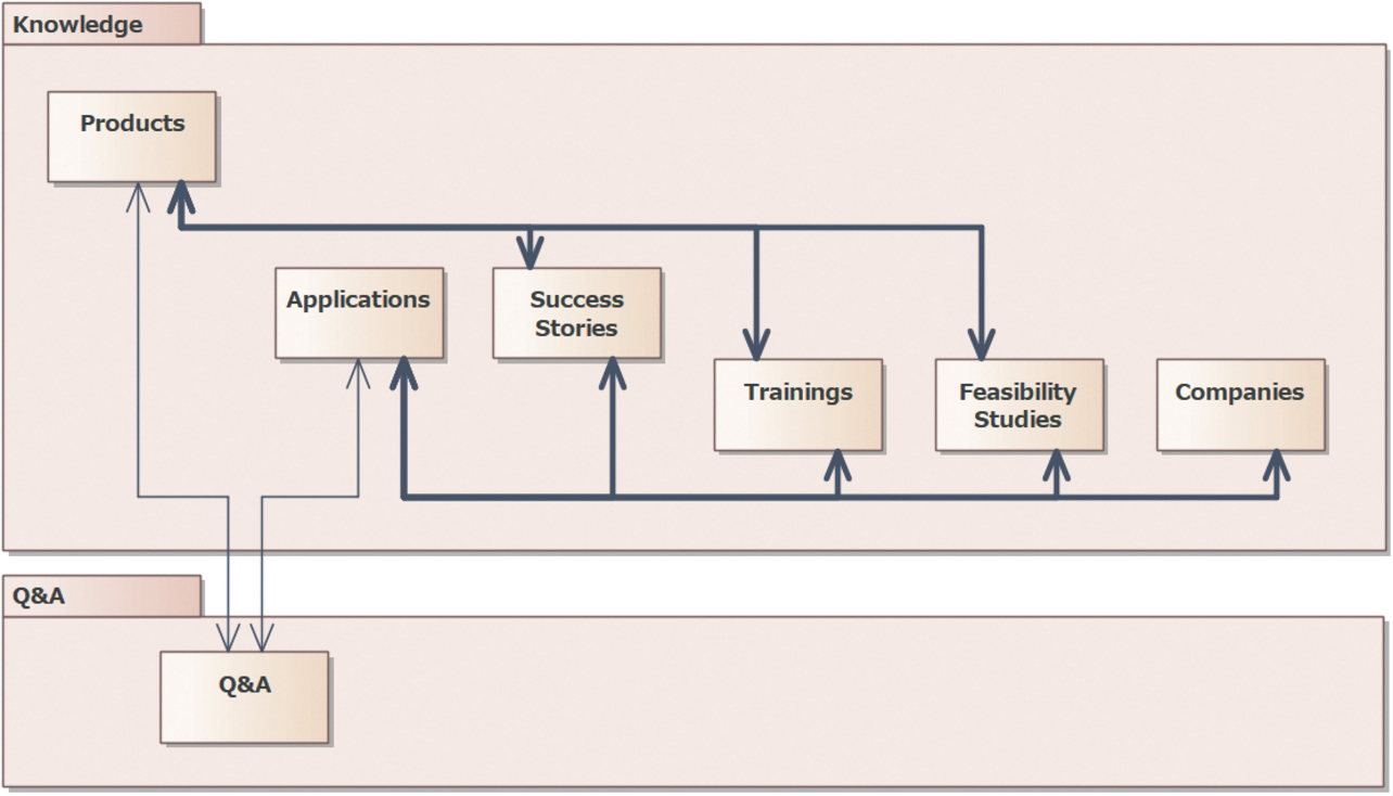
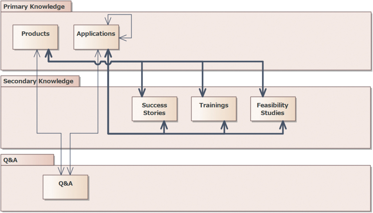
Fig. 3 shows the results of modeling the new system. The following points are represented here:
- Technological knowledge types are divided into Primary and Secondary Knowledge categories, with technological knowledge types, including “Success Stories,” subordinated to the technological knowledge type “Applications.”
- For the technological knowledge type “Applications,” associations between “Applications” can be set, taking into consideration use cases in which registered technological knowledge serve as the base for registering other technological knowledge.
- The technological knowledge type “Companies” is officially made outside the control of our system from the perspective of the division of system responsibilities.
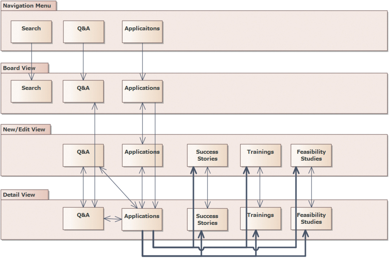
(2) Static site maps
Fig. 4 shows the results of modeling the current system. Note that the thick lines in the figure represent transitions between “Applications” and other screens. The following points are represented here:
- The access to the technological knowledge type “Applications” is represented as a leading line from “Industries” in the Navigation Menu.
- The standard screens (those with a name starting with SP from among screen categories) and custom screens are used in combinations, resulting in many screens and complicated screen transitions.
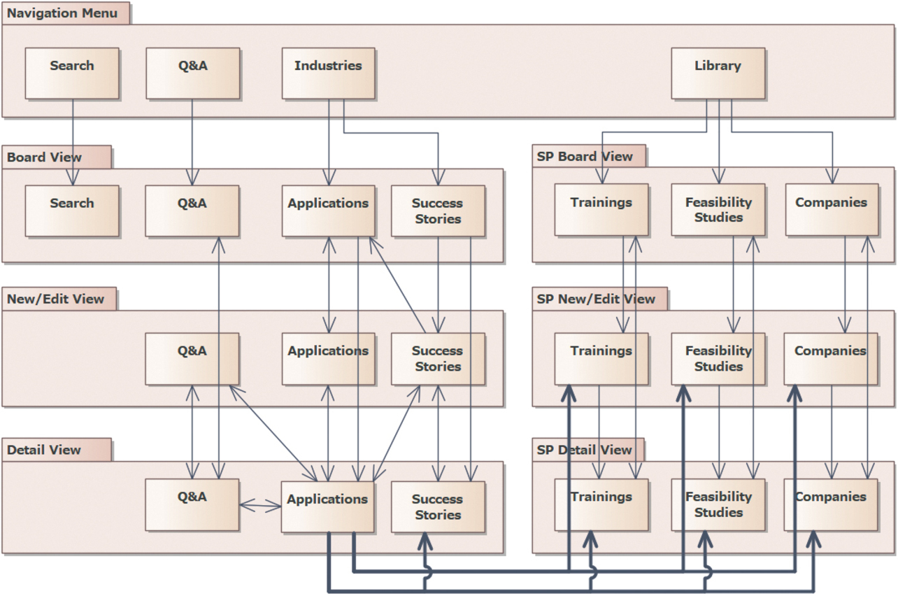
Fig. 5 shows the results of modeling the new system. The following points are represented here:
- The technological knowledge type “Applications” appears in the Navigation Menu.
- Each access to Secondary Knowledge is represented as a leading line from Primary Knowledge.
- Only custom screens are retained to reduce the number of screens and to simplify screen transitions.
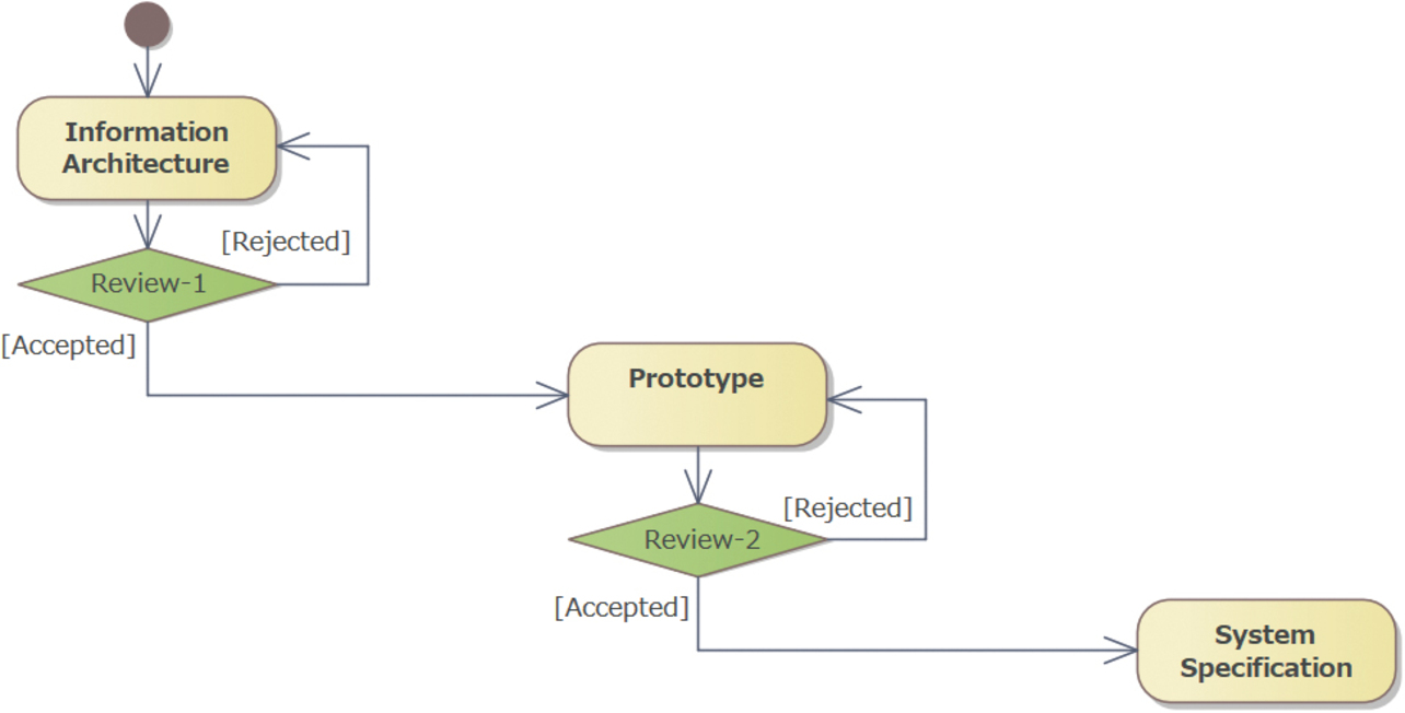
3.3 Model reviews and system specifications
We repetitively reviewed models with the base representative users to establish a shared understanding. These models served as the basis for developing the system specifications. However, the system specification sheets were challenging for the base representative users to understand. Therefore, we developed a prototype for review by the base representative users while we provided the system specification sheets for review by the in-house parties concerned and developers. Fig. 6 shows the model and prototype review flow.
4. Effectiveness verification
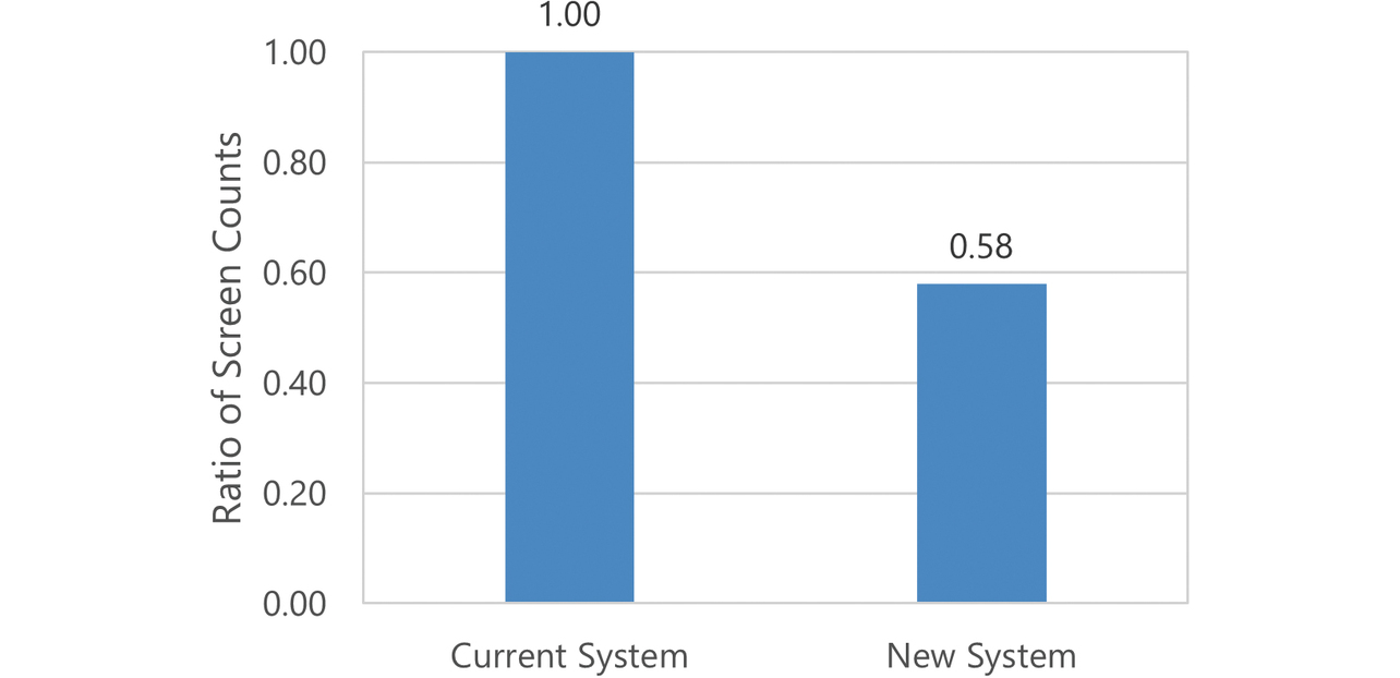
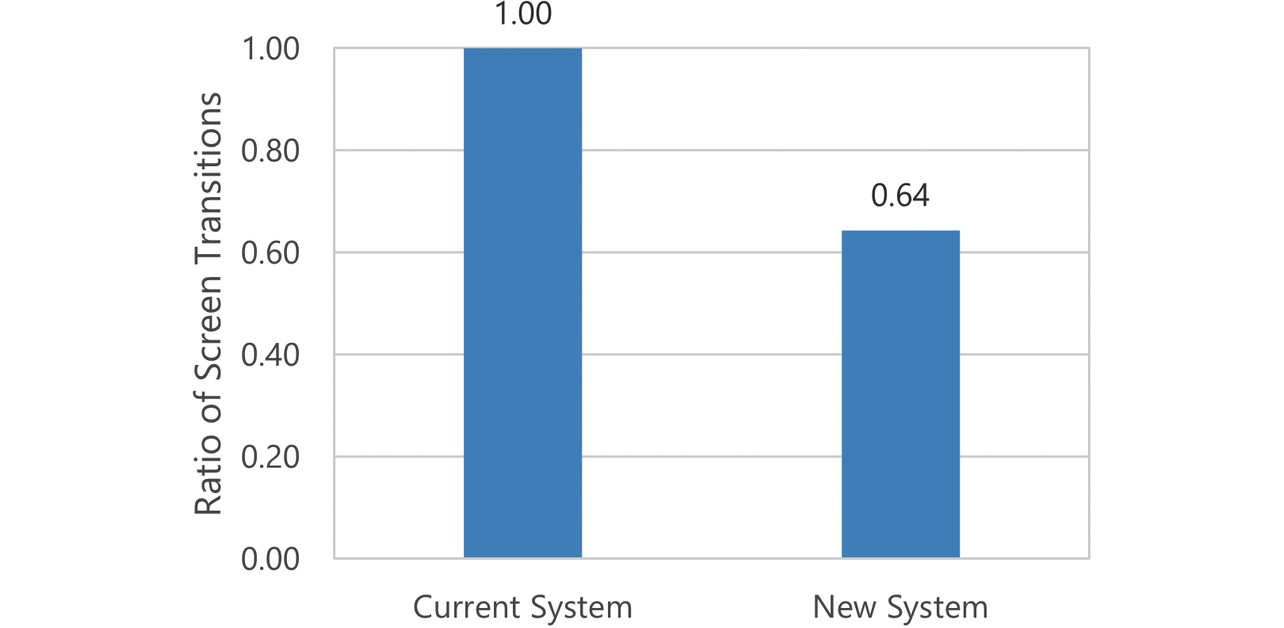
4.1 For Challenge (1)
Figs. 7 and 8 show the ratio of the number of screens and the ratio of screen transitions between the current and new systems, respectively. Screens and screen transitions decreased in number by 42% and 36%, respectively.
Based on representative use cases and those pointed out to have low usability, we created ten scenarios from A to J to simulate operations on the dynamic site maps. Figs. 9 and 10 show the numbers of operations and screen transitions made by the users for each scenario, respectively. Operations and screen transitions decreased in total number by 30% and 27%, respectively.
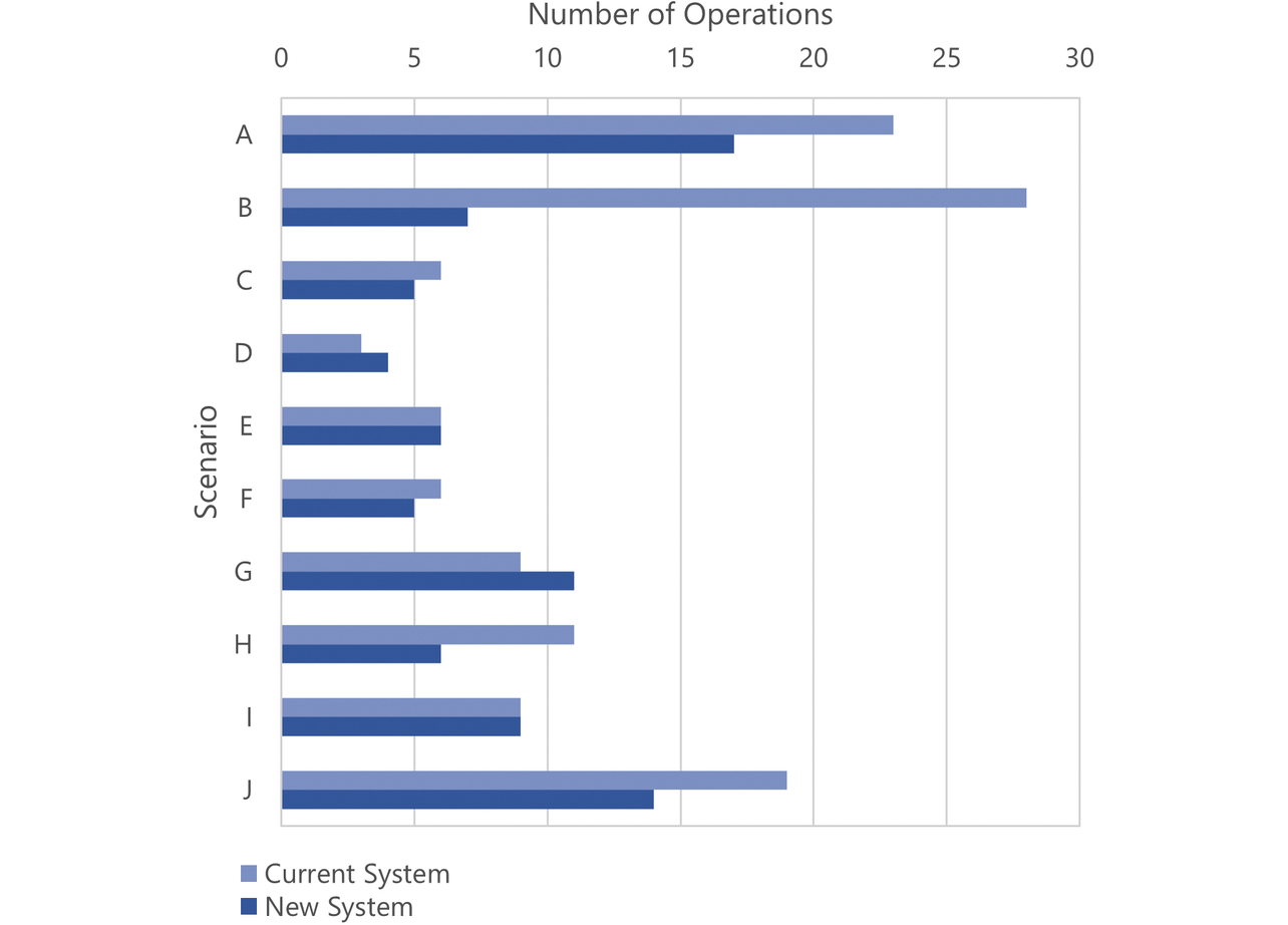
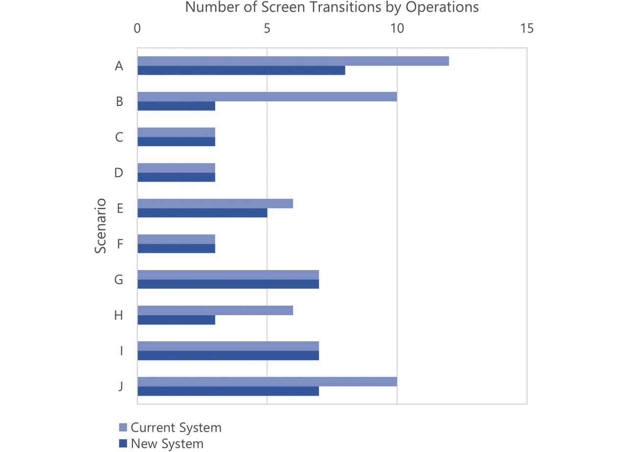
Operations and screen transitions significantly decreased in number for Scenarios A, B, and J. This effect resulted from the streamlining of screens to custom screens and the consolidated installation of screens at the home site. The number of operations slightly increased for Scenarios D and G. These increases resulted from operations to reshow UIs hidden for screen decluttering and were tolerated because they would not affect screen transitions. Considering that screens and screen transitions were reduced in number as seen above and that the numbers of operations and screen transitions dropped in simulations of our system in actual use, we can say that the users’ operation efficiency was successfully improved.
4.2 For Challenge (2)
The current system had “Applications” and “Success Stories” in the same level menus, allowing separate registration of technological knowledge falling under “Success Stories.” In other words, technological knowledge falling under “Success Stories” were not necessarily required by the system to be associated with that falling under “Applications” but could be freely associated at the user’s discretion.
The new system has Primary and Secondary Knowledge categories for technological knowledge types. This system has had leading lines reviewed with “Applications” appearing at the highest-level menu. Moreover, its specifications have been reviewed to register technological knowledge falling under “Success Stories” as part of that falling under “Applications.” In other words, the system guarantees that any technological knowledge falling under “Success Stories” is always registered in association with that falling under “Applications.” However, these specifications will expectedly lead to increased opportunities to register technological knowledge falling under “Applications.” Accordingly, we reviewed the specifications to allow registration of technological knowledge as derivatives of that falling under similar “Applications,” if any. Thus, we have considered reducing the registration workload.
We considered whether guaranteeing such a systematic accumulation of technological knowledge will make chain referencing possible, helping to improve the users’ utilization efficiency.
4.3 For system specification alignment
We performed the reviews shown in Fig. 6 and completed responses to the findings. These responses have been fed back to the model. Fig. 11 shows the ratio of findings between the two reviews.
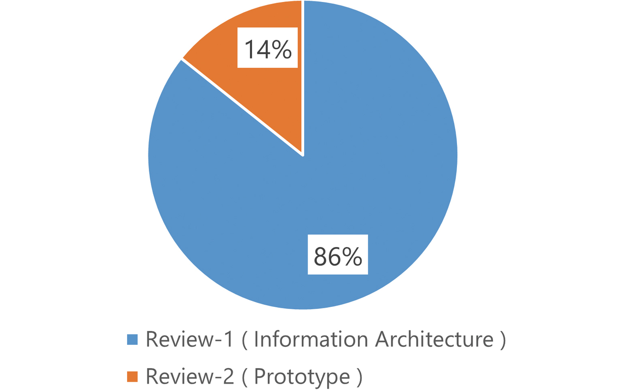
The information architecture accounts for 86% of the total number of review findings. The shared understanding established with the base representative users during the review phase for the information architecture has probably led to fewer review findings on the prototype. Such a shared understanding of the information architecture has enabled the system specifications to be efficiently brought into overall optimal alignment.
5. Conclusions
The challenges to efficient technological knowledge sharing were (1) frequent cross-screen operations and (2) weak relationships between accumulated technological knowledge. Moreover, system specification alignment with the base representative users would involve difficulties due to barriers posed by language differences and knowledge gaps.
To address these challenges, we used information architecture modeling to model the information architecture intrinsic to the current system. Then, we created model representations of the new system capable of improving the systematic accumulation of technological knowledge and enabling efficient technological knowledge sharing while reducing cross-screen operations. We established a prior shared understanding of the model among the base representative users to overcome the barriers posed by language differences and knowledge gaps and efficiently bring the system specifications into overall optimal alignment.
We will start a development project to give a tangible form to these system specifications. This development will involve visual design adaptations not considered in the planning phase. Although custom-configured screens may increase the development cost of the new system, we will componentize and reuse user interfaces to add efficiency to the development for an earlier release.
The requirements for a system will change as time and circumstances change. Returning to the inter-element balance required of an information architecture, we will work on model revisions and system improvements carefully and flexibly.
References
- 1)
- Y. Akamatsu, “Establishment and Utilization of Technological Knowledge Global Sharing System,” (in Japanese), OMRON TECHNICS, vol. 55, no. 1, pp. 108-114, 2023.
- 2)
- L. Rosenfeld et al., Information Architecture: for the Web and Beyond, T. Shinohara, Japanese edition, translated under the supervision., 4th ed. O’Reilly Japan, 2016.
- 3)
- A. Hasegawa, Information Architecture Design for User Experience Design, (in Japanese), BNN Shinsha, 2009.
- 4)
- T. Demarco, Structured Analysis and System Specification, T. Takanashi and J. Kuroda, Japanese edition, translated under the supervision., Nikkei BP, 1994, pp. 265-320.
The names of products in the text may be trademarks of each company.