


Establishment of Partial Plating Technology that Realizes Device Performance with the Minimum Necessary Precious Metals
- Partial Plating
- Surface Treatment
- Metering liquid feeder
OMRON continues to take on the challenge of contributing to the spread of renewable energy equipment and high-speed communication equipment by providing devices and modules toward the realization of a carbon neutral and digitalized society. In order to realize these device performances, advanced product design technology and production technology that incorporates quality in the manufacturing process are important. In particular, electroplating is an important technology that modifies the surface of materials at low cost and realizes device performance (contact reliability, corrosion resistance, etc.). The contact part of the MIL connector, which is used for the inter-board connection of solar power generation inverters that require outdoor contact reliability, is electroplated with gold plating.
In this paper, in order to reduce the amount of gold used for the purpose of reducing the environmental impact, we developed and mass-produced a partial plating technology that contacts the gold plating solution only where it is necessary to realize the product performance of MIL connectors. Although the same product performance as conventional connectors has been achieved with a plating area of 1/3, we will introduce the details.
1. Introduction
OMRON continuously takes on challenges to contribute as a device and module supplier to a broader use of renewable energy and high-speed communication equipment to realize a carbon-neutral digital society. There are two keys to achieving such device performance. One is advanced product design technology, and the other is production technologies for achieving built-in quality during manufacturing.
Among such technologies, electroplating is a constituent technology of critical importance that modifies material surfaces at low cost and achieves the required device performance (including contact reliability and corrosion resistance); it is an indispensable surface treatment technology still widely used globally.
However, electroplating manufacturing processes use chemical agents and hence require wastewater treatment. Moreover, these processes use precious and rare metals as raw materials and thus have the drawback of having high environmental loads due to environmental destruction during metal resource mining or CO2 emissions from ore dressing and smelting.
OMRON is committed to two efforts to reduce these environmental loads as much as possible.
The first effort is the treatment of chemical agents. Following its recent rapid development, China has been tightening its environmental regulations on plating wastewater every year. OMRON China’s Shenzhen factory has improved its drainage facilities to adapt to the tightening wastewater standards.
The second effort is a more efficient use of precious and rare metals. Efforts are underway to reduce precious metal usage by performing plating only where needed according to well-defined plating specifications (material, film thickness, and range) that meet the required performance of electronic parts, such as relays, switches, and connectors.
Let us take, for example, MIL connectors adopted for inter-board connection of solar power generation inverters. These connectors have their contact portion gold plated because they must provide contact reliability outdoors. However, gold is plated even where not needed for product performance.
This paper presents the details and characteristics of the partial plating technology we developed for mass production in which the gold plating solution is allowed to come into contact only where gold plating is needed for the performance of the MIL connector plug terminal, thereby achieving contact reliability with the minimum necessary amount of gold.
2. Conventional partial plating technology
2.1 Current state and challenges in standard partial plating
Partial plating methods generally adopted in the plating industry include the partial dip and brush plating methods1).
Fig. 1 shows an overview of the brush plating method. A porous material tube with a built-in anode is allowed to absorb the plating solution so that plating occurs where the solution contacts the material to be plated. Taking a MIL connector plug terminal as an example, this section describes the current state and challenges in standard partial plating methods. Because the plating solution contacts the plug terminal’s porous material-contacting face and side faces, three faces get gold plated per plug terminal pin. Considerable variations occur in plating film thickness because of the variable contact area of the plating solution and the plug terminal. In addition, gold is deposited on the porous material surface contacting the plug terminal and must be removed at regular intervals, posing a problem with mass productivity.
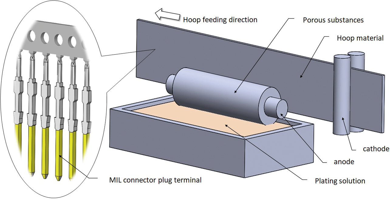
Thus, the brush plating method has problems with all of the following: plating range (raw material usage), quality (plating film thickness accuracy), and mass productivity (system maintenance frequency).
2.2 Current state and challenges in OMRON’s conventional method of partial plating
Since 2005, OMRON has been developing and mass-producing its proprietary partial plating technologies based on the horizontal drum method.
Fig. 2 shows an overview of OMRON’s conventional partial plating system. Fig. 3 shows the conventional partial plating apparatus comprising an electrolyte circulation unit, its internal circuit, and a material feeding unit to be plated. This apparatus is built with an anode disposed inside the electrolyte circulator to circulate the electrolyte from above to downward through a gap with the material to be plated. The apparatus wraps a press-processed hoop material around the material to be plated feeding unit to continuously feed and plate the material.
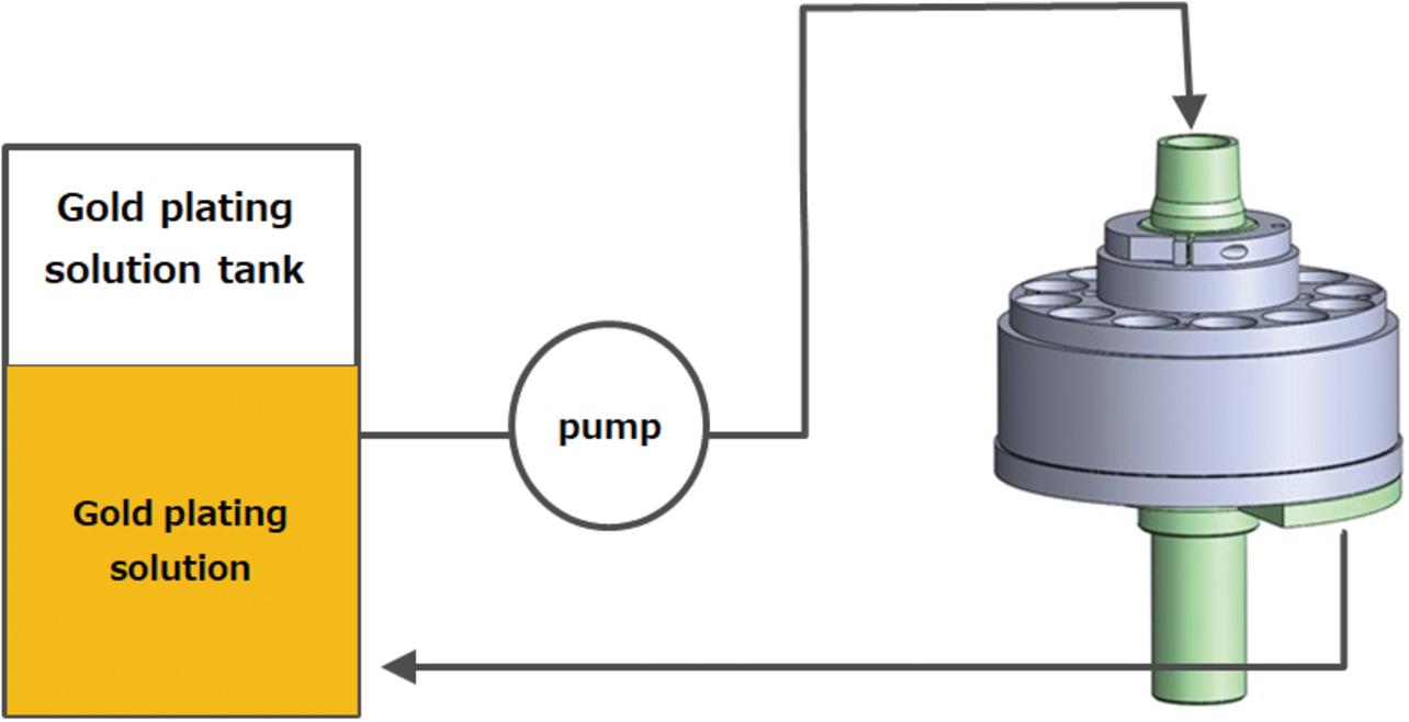
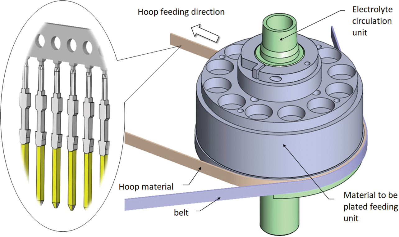
Fig. 4 shows a sectional view of the conventional partial plating apparatus. This apparatus maintains a uniform ion concentration in the electrolyte while maintaining a fixed distance between the cathode-equivalent material to be plated (plug terminal) and the anode to ensure that the plug terminal’s plated face is uniformly charged with electricity, successfully reducing variations in the plating film thickness. Moreover, with only the plating solution in physical contact with the plug terminal’s electric field applying portion, the apparatus remains free from anomalous gold deposits, successfully reducing the system maintenance frequency to once a week or less. Thus, the quality and mass productivity targets required for the MIL connector were achieved.
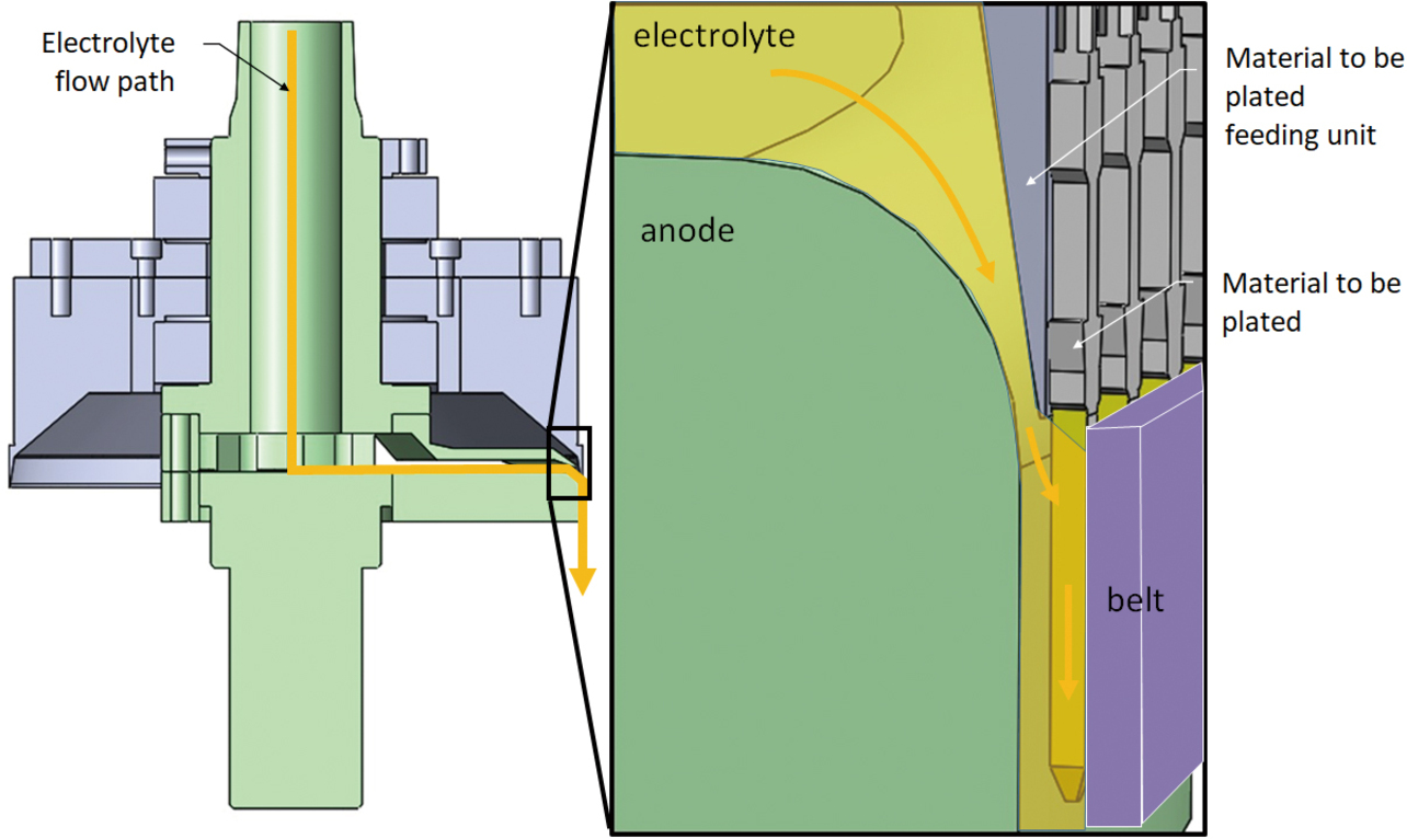
However, this method was left with the problem of plating usage because gold is plated on the plug terminal’s side faces, which do not need gold plating for product performance. While circulating, the electrolyte contacts the plug terminal’s electrolyte-contacting face and side faces, resulting in a plug terminal that is gold plated on three sides. With a belt feeding the hoop while holding it down on its rear side, the belt-contacting side does not get gold plated.
Generally speaking, when an electrolytic reaction causes metal deposition or dissolution, Faraday’s Laws hold between the amount of electricity involved and the reaction product2).
- First Law: In electrolysis, the amount of metal deposited on the cathode or dissolved on the anode is proportional to the amount of electricity involved.
- Second Law: The amount of metal deposited or dissolved with the same amount of electricity is proportional to their respective metal electrochemical equivalent.
In the case of electroplating, electrolysis is performed through the electrolyte (plating solution). Hence, gold plating occurs even where gold plating is not needed for product performance if any electrolyte exists.
In other words, we had to develop an apparatus for which the following two conditions hold to ensure stable mass-production of partial plating:
- Condition 1: The electrolyte is allowed to contact an appropriate site on the material to be plated.
- Condition 2: The ion concentration in the electrolyte is kept constant.
2.3 Current state and challenges in plating for MIL connectors
MIL connectors are harness-type connectors with MIL spec-compliant flat cables (MIL-C-83503) connected by pressure welding into a harness. Available with a wide range of lock variations, such as custom sockets with a lock or custom quick locks, in addition to MIL types, these connectors are also adopted for inter-board connection of solar power generation inverters, which requires contact reliability outdoors. Fig. 5 shows the appearance of a MIL connector.
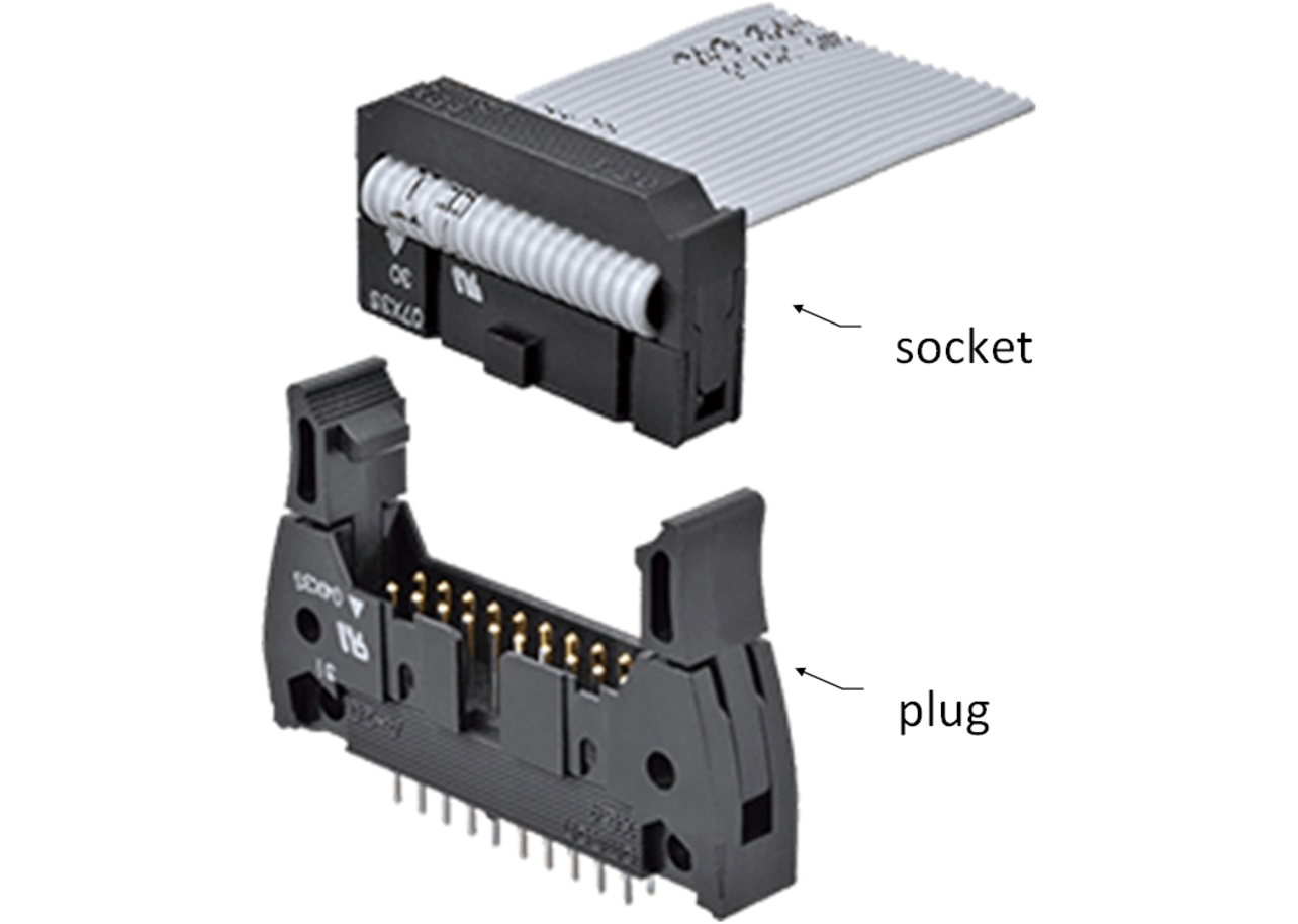
A MIL connector consists of a plug mated with a socket, with only one plug-socket contact surface.
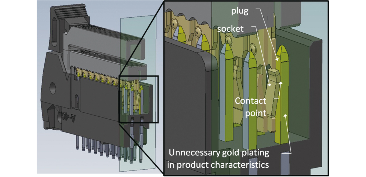
In the plug terminal, only the plug-socket contact surface needs gold plating for product performance. Besides this contact surface, however, the plug terminal’s side faces are also gold-plated unnecessarily. Fig. 6 shows conventional plated parts in contact condition.
3. Newly developed partial plating technology
3.1 Partial plating technology developed this time
Our newly developed partial plating technology consists of the three apparatuses below, ensuring that the two conditions for stable mass production hold, as presented in Subsection 2.2. Fig. 7 shows an overview of the partial plating system.
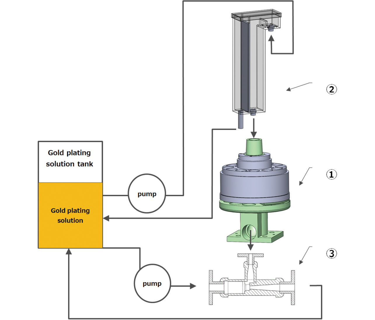
- (1) Electrolyte circulator/material feeder to be plated
- (2) Constant-rate electrolyte feeder
- (3) Electrolyte suction unit
The following sections describe the functions of these apparatuses.
3.2 Electrolyte circulator/material feeder to be plated
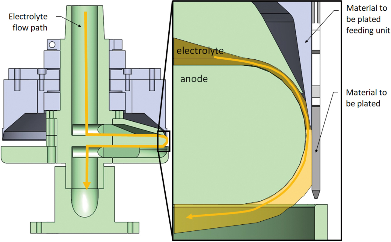
The electrolyte circulator/material feeder to be plated features the ability to feed the material to be plated while selectively contacting the electrolyte to the material to be plated. This apparatus comprises an electrolyte circulation unit, its internal circuit, and a material to be plated feeding unit. Fig. 8 shows the appearance of this apparatus.
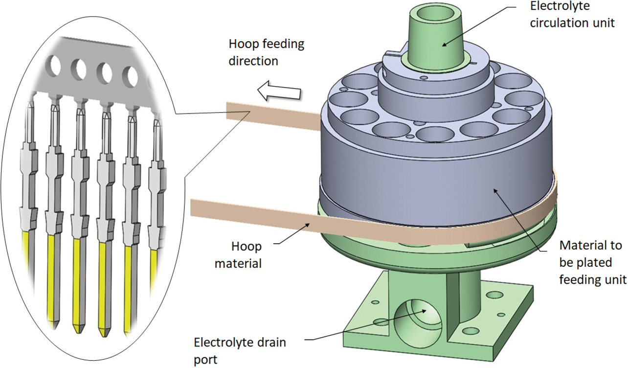
This apparatus is provided with a slit-like window part opened to the exterior of the electrolyte circulation unit. Its material to be plated feeding unit feeds the material to be plated while aligning the plateable area on one side of the material to be plated with the window part.
This configuration allows the electrolyte to contact only one side of the material to be plated and circulate, thereby enabling partial plating with the ion concentration in the electrolyte kept constant. The electrolyte circuit contains an arc-shaped portion in which the electrolyte flows past the slit-like window part from the surface of the material to be plated away in the normal direction. This phenomenon is called the Coanda effect, which describes the tendency of a jet of viscous fluid attracted to a nearby wall. Fig. 9 shows the relative positions of the anode, the material to be plated (MIL connector plug terminal), and the electrolyte. One can see that the electrolyte is attracted to the round portion of the anode and into contact with only one side of the material to be plated.
3.3 Constant-rate electrolyte feeder
The constant-rate electrolyte feeder features the ability to maintain a constant ion concentration in the electrolyte and feed the electrolyte to Apparatus ① at a constant feed rate. For the required function of Apparatus ① to be met, the electrolyte circuit’s volume (A) and the fed amount of electrolyte (B) must be equal to each other. The loss of the balance between the former and the latter leads to the following defects:
- A < B: Occurrence of gold depositions where not needed and plating film thickness variations
- A > B: Occurrence of bare spots and plating film thickness variations
At the start of development, we considered flowrate sensor-based feedback control, which failed to suppress pump pulsation, besides electrolyte feed rate variations caused by response speed delays. We also feared the risk of bare spots, which might occur when air bubbles get entrapped in the electrolyte being pumped up and sit in between the anode and the material to be plated. Based on these considerations, we defined the functions required of a constant-rate electrolyte feeder as the following two:
- (1) Function 1: Suppressing pump pulsation and bubbling in the electrolyte; and
- (2) Function 2: Controlling the electrolyte to a constant feed rate.
Fig. 10 shows a sectional view of our newly developed constant-rate electrolyte feeder. The above functions are implemented by the following structures, respectively:
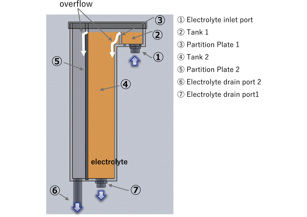
(1) Structure 1: Overflow structure
The electrolyte pumped up from the control tank is fed through ① the Electrolyte inlet port to ② Tank 1 and flows over ③ Partition Plate 1 to be fed to ④ Tank 2 when Tank 1 is filled up. When Tank 2 is filled up, the electrolyte flows over ⑤ Partition plate 2 to return from ⑥ Electrolyte drain port 2 to the control tank. The two overflows absorb pump pulsation and cause air bubbles in the electrolyte to be released from the top liquid level of Tanks 1 and 2.
(2) Structure 2: Liquid level height/flow path area fixing structure
⑦ The flow rate Q of the electrolyte discharged from Electrolyte Drain Port 1 is obtained from the following equation:3)

- Q : Flow rate (m3/s)
- C : Flow rate coefficient
- A : Flow path area (m2)
- g : Gravitational acceleration (9.8 m/s2)
- h : Liquid level height (m)
The above equation means that the flow rate Q can be controlled to a constant value by fixing the liquid level height h and the flow path area A. The liquid level height h can be fixed at the height of ⑤ Partition Plate 2 with the electrolyte circulating as explained regarding Structure 1. The flow path area A, or the flow path opening area, can be fixed by adjusting the opening amount of the valve provided at ⑦ Electrolyte Drain Port 1.
3.4 Electrolyte suction unit
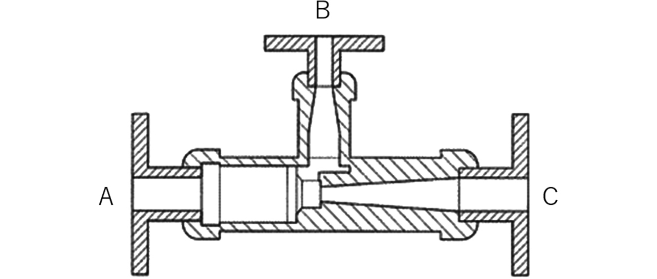
We adopted a commercially available general-purpose ejector for the electrolyte suction unit. Fig. 11 shows a sectional view of the electrolyte suction unit. This unit is built so that suction force occurs to Port B when the electrolyte is fed from Port A to Port C. When Port B is connected to the electrolyte drain port of the electrolyte circulator (see Fig. 8), an electrolyte suction effect occurs that assists the Coanda effect.
4. Effectiveness verification
4.1 Verification results
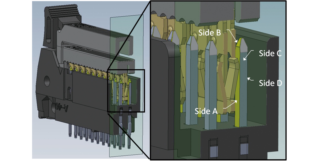
Our newly developed partial plating technology led to reducing the plating area per MIL connector plug terminal pin to one-third of that before, enabling gold plating only where needed for product performance. Table 1 shows the plated condition of the MIL connector plug terminal before and after the improvement. Fig. 12 shows the improved plated parts inside the MIL connector in mated condition. One can see that the gold plating on the plug terminal’s side faces was successfully reduced.
| Plated condition | Side A | Side B | Side C | Side D | Gold plating |
|---|---|---|---|---|---|
| Before improvement |  |
 |
 |
 |
3 faces |
| After improvement |  |
 |
 |
 |
1 face |
The improved plug showed contact reliability similar to that before the improvement.
4.2 Comparison per partial plating method
Table 2 shows the results of comparing the plating methods against the requirements for the MIL connector. Our newly developed partial plating technology (OMRON new method) achieved all of the development targets in terms of raw material usage (plated faces), quality (plating film thickness accuracy), and mass productivity (system maintenance frequency).
| Partial plating method | Partial dip method | Brush plating method | Omron conventional method | Omron new method |
|---|---|---|---|---|
| Raw material usage (plated faces) | × | △ | △ | ○ |
| Quality (plating film thickness accuracy) | × | × | ○ | ○ |
| Mass productivity (system maintenance frequency) | ○ | × | ○ | ○ |
Legends
- Raw material usage (plated faces):
○=1 face; △=3 faces; ×=4 faces - Quality (plating film thickness accuracy):
○=small variations; ×=large variations - Mass productivity (system maintenance frequency):
○=once a week or less; ×=more than once a week
5. Conclusions
MIL connectors adopted for inter-board connection of solar power generation inverters have their contact portion gold plated because they are required to provide contact reliability outdoors. We worked on reducing the usage of indispensable gold plating to achieve the contact reliability required of MIL connectors. We achieved a plating area three times smaller than before, along with contact reliability similar to that before. Consequently, the precious metal usage in our system decreased, resulting in less of an environmental load.
The final form of partial plating technology we pursue is such that enables selective plating only on any point on any shape. Moving forward, we intend to pursue general-purpose technology development toward the fruition of this goal and deploy the outcomes to relay switch devices.
Plated parts mounted onto OMRON’s devices are produced by global suppliers. We hope to spread the use of the partial plating technology developed this time on the production sites of our suppliers to contribute to reducing precious metal usage and environmental loads.
References
- 1)
- Y. Nishimura and M. Hiramatsu, “Introduction of Various Partial Plating Methods for Connector Terminals,” (in Japanese), Surf. Technol., vol. 68, no. 2, pp. 80-83, 2017.
- 2)
- Y. Ishihara et al., Fundamentals of Plating for Adaptation to High Technologies, (in Japanese), Maki Shoten, 1994.
- 3)
- H. Sugiyama et al., Straightforward Introduction to Fluid Mechanics, (in Japanese), Morikita Publishing, 2012.
The names of products in the text may be trademarks of each company.