3D Imaging of Outdoor Human with Millimeter Wave Radar using Extended Array Processing
- Millimeter-wave Radar
- 3D Imaging
- Infrastructure Sensor
- Driving Safety Support Systems
- Doppler Radar
Research and development on cooperative vehicle infrastructure systems are being promoted for realizing a safe and smooth transportation society. Information from sensors installed in the road infrastructure is used for this system. Millimeter-wave radar is attracting much attention as a next-generation infrastructure sensor that is less affected by the weather, such as rain and dense fog, and can detect targets day and night. 3D imaging with narrow beam is effective for millimeter-wave radar to separate and identify various targets in an environment such as intersections. A planar array consisting of a large number of receiving antennas is required for 3D imaging, but it was difficult to achieve a narrow beam because the number of antennas is insufficient with one IC chip. On the other hand, using multiple IC chips causes problems, such as hardware complexity and radar size increase. To overcome these problems, we applied extended array processing to one chip millimeter-wave radar and tried to realize a narrow beam by a virtual planar array with an increased number of virtual antenna elements in the vertical and horizontal directions. As a result of 3D imaging of outdoor humans, we confirmed the detection of human outlines and showed improvement in target distinction.
1. Introduction
The number of fatalities in traffic accidents has been on a decreasing trend in recent years, and according to the National Police Agency, the number of fatalities in a 24-hour period (the number of people who die within 24 hours of a traffic accident) decreased to less than 3,000 in 20201). However, this still falls short of the goal set by the government in the 10th Traffic Safety Basic Plan to reduce the number of fatalities in a 24-hour period to 2,500 or less by 2020, and many lives have been lost in traffic accidents. The 11th Traffic Safety Basic Plan, which was established in 2021 with the goal of realizing safer road traffic, aims at reducing the number of fatalities in a 24-hour period to 2,000 or less by 20252).
In addition, the governmentŌĆÖs ITS Concept / Roadmap 2020 for the public/private sectors sets a goal to build the worldŌĆÖs safest and smoothest road transport society by 2030, and the desire is to build a society that is not only safe but also contributes to reducing the environmental load by mitigating traffic congestion and realizing smooth road transport3). In order to achieve this goal, research and development on automated driving using the cooperative vehicle infrastructure systems is being promoted. Cooperative vehicle infrastructure systems utilize the information from road traffic infrastructure in addition to the information from sensors onboard the vehicle. It is suggested as a requirement for the road traffic infrastructure to acquire information on surrounding vehicles and pedestrians that cannot be recognized by vehicles, and the sensors are required on the infrastructure side to provide this information to the vehicles and drivers.
Millimeter-wave radar, which irradiates radio waves to a target and detects the distance and speed to the target using the reflected waves, has the feature of not easily being affected by rain or fog or affected by the lighting conditions, such as sunlight. For this reason, it is attracting attention as a next-generation infrastructure sensor that can realize the above-mentioned safe driving support and smooth traffic.
The authors have been developing millimeter-wave radar as an infrastructure sensor that monitors and controls the traffic conditions and have been studying 2D imaging radar for detecting vehicle positions based on distance, speed, and azimuth (angle of orientation) information4). In addition, during the course of development, in order to execute accurate object detection using the radar, we are considering a study regarding 3D imaging of objects using distance/speed information and azimuth and elevation angle information5) and to use it not only for road monitoring aiming at the detection of vehicles but also for use in environments where people and vehicles coexist. This paper details the 3D imaging of outdoor persons using millimeter-wave radar.
2. Measuring Principle of Millimeter-Wave Radar
2.1 Measurement of Distance/Velocity
There are various types of radar systems; the measuring principle is explained here for distance and speed using the frequency modulation continuous wave (FMCW) radar system adopted in this study. FMCW radar transmits a frequency-modulated signal called a chirp signal as shown in Fig. 1 and measures the distance R to the target using a beat signal having a difference frequency component obtained by mixing the received signal reflected by the target and the transmitted signal. Since the received signal is delayed with respect to the chirp signal according to the round-trip propagation distance between the radar and the target, the frequency Δf of the beat signal is proportional to the delay time τ = 2R /c0, in other words, the distance to the target, and the following relationship holds:

where, B is the sweep frequency bandwidth, T is the frequency sweep time, and c0 is the speed of light. The distance between the radar and the object is calculated by the Fourier transform of the beat signal and the reading of the peak information corresponding to the object response from the frequency spectrum. When the target is moving, a frequency component corresponding to the relative velocity between the radar and the target (Doppler frequency fd ) is superimposed on the received signal due to the Doppler effect. The following relationship holds between the Doppler frequency and the relative velocity v :

where, f0 is the center frequency used in FMCW radar, and λ0 is the wavelength corresponding to the center frequency. The Doppler frequency is obtained by executing the Fourier transform of the received signal obtained by transmitting and receiving the chirp signal multiple times and reading the peak information of the frequency spectrum. The detectable maximum Doppler frequency depends on the transmission cycle Tr , and the shorter the transmission cycle, the higher Doppler frequency is detected. The maximum detectable Doppler frequency uniquely determined from the sampling theorem is 1/(2Tr ), and the corresponding velocity is λ0/(4Tr ) by applying the coefficients generated during the conversion between Doppler frequency and relative velocity in equation (2).

2.2 Measurement of Angle
Where the radar consists of an array antenna configured with multiple antennas and the distance between the target and the radar is sufficiently larger than the array aperture, the incident wave from the target to the radar may be regarded as a plane wave. In this case, the reflected signal from the target to the radar is incident with a path length difference based on the relative angle between the radar and the target per each receiving antenna. Because of this, a difference in the amount of delay based on the path length difference, in other words, the phase difference is generated between the received signals by each receiving antenna. Based on this phase difference, the angle of the target with respect to the radarŌĆÖs line of sight can be calculated. The angle is calculated by Fourier transforming the received signal obtained via the array antenna and reading the peak information of the obtained frequency spectrum. Fig. 2 shows the path length difference for each receiving antenna in a uniform linear array (ULA) of receiving N elements.

Additionally, when the ULA is placed horizontally, the azimuth angle is measurable, and when vertical, the elevation angle is measurable. When simultaneously detecting the azimuth and elevation angles, the planar array antennas are used, where the antennas are arranged on a plane.
3. Functions Required for Enhanced Accuracy of Target Detection
As shown in Fig. 3a, a radar with horizontally aligned receiving array antennas is used in 2D imaging radar that detects the target positions based on distance, velocity, and azimuth information where, R is the distance between the radar and the target, and θ is the angle (azimuth angle) between the radar line of sight and the target. Furthermore, by using a planar array antenna as the receiving antenna similarly as the 3D imaging radar that detects the target position based on the distance, velocity, azimuth, and elevation angle information as shown in Fig. 3b, the elevation angle φ is detectable in addition to the distance, velocity, azimuth angle information detectable with 2D imaging radar. When radar is used for monitoring the traffic intersections and roadways, reflected waves are received not only from persons but also from various objects and targets, such as vehicles, buildings, signs, and road markers. In conventional 2D imaging using distance, velocity, and azimuth information via radar with array antennas in the horizontal direction, the target position and velocity are detected in the horizontal plane identical with the array antenna arrangement, as shown in Fig. 4a. However, the altitude information of the target is projected onto this plane, and targets at different altitudes are detected in the same plane. Because of this, it will be difficult to identify the shape of objects that have a vertical spread. In addition, the velocity information is expected to be used by infrastructure sensors to determine the degree of risk due to approaching vehicles, whether a vehicle is driving in the wrong direction, and to detect speeding, but the detectable velocities by 2D imaging radar are detected as the values in an identical plane. When the direction of movement of the target is different from the direction of the radarŌĆÖs line of sight, such as when the radar is mounted at a high altitude to observe an object on the ground surface, the accuracy of the object velocity information will be degraded. On the other hand, 3D imaging uses radar with array antennas in the horizontal and vertical directions to measure the arrival angle information, including not only the azimuth angle but also the elevation angle. By using elevation angle information in addition to distance, velocity, and azimuth angle information, the 3D spatial distribution information (3D imaging) of the target will be acquirable as shown in Fig. 4 b, and it will be possible to separately detect the shape of target at different altitudes, the shape of the target in a 3D space seen from the radar will be recognizable, and bring about ease of target identification or status recognition (posture of a person, etc.)


In addition, by using the elevation angle information and azimuth angle, it is possible to decompose the velocity information of targets into a 3D space, which enables more accurate detection of target velocities in such a case where the radar is installed at a high altitude to observe objects on the ground surface, which has been a problem with 2D imaging radar. Infrastructure sensors are presumed to be installed at high altitude to observe the ground surface in order to detect targets that are difficult to detect with the vehicle onboard sensors. In this case, it tends to receive reflected waves not only from persons and vehicles but also from objects at different altitudes, such as signs and billboards in the vicinity. For this reason, it becomes necessary to provide more accurate information by separating by height using 3D imaging and by decomposing the object movement velocity using the azimuth and elevation angle information.
In such a situation where there are multiple targets within the radar observation space, it is necessary to achieve a narrow beam that can separate and detect individual target positions, in other words, to enhance resolution. Radar, which detects object information from radio wave reflection, can easily detect distance and velocity, and the distance resolution can be enhanced by increasing the frequency bandwidth and the velocity resolution by increasing the observation time. However, when multiple objects seen by the radar are traveling in parallel close together, separation in terms of distance and velocity becomes difficult. Among all, persons are more difficult to reflect radio waves than vehicles, so it becomes difficult to separately detect by distance or velocity when multiple persons are in close proximity as shown in Fig. 5. Accordingly, in order to separately detect multiple objects, such as persons or vehicles, in close proximity, a narrow beam in the angular direction becomes necessary.

From the above, it is considered that the narrow beam in the angular direction and distance and velocity are necessary to separately detect target objects observed by radar, and that 3D imaging is effective to identify targets at different altitudes and to identify the shape and state of the target objects. The planar array antennas with a large number of receiving antennas are required for 3D imaging with narrow beams. However, current IC chips for millimeter-wave radars generally consist of three transmitting antennas and four receiving antennas per chip, and the number of antennas is insufficient for a single chip, making 3D imaging with a narrow beam difficult. The use of multiple chips will improve the insufficient number of antennas, but the hardware configuration becomes more complex, and the use of a large number of array antennas will lead to a larger radar system. For solving this problem, the authors applied the narrow beam technology described in the next chapter to single-chip millimeter-wave radar to construct a planar array antenna and attempted 3D imaging of targets.
4. Narrow Beam Technology
In order to achieve a narrow beam in the angular direction, it is necessary to increase the array aperture length, in other words, to increase the number of antenna elements that configure the receiving array antenna. However, an increase in the number of antenna elements is problematic because of the limitation on the number of antennas by the radar IC chip, which leads to more complicated hardware and larger radar due to the use of multiple chips. For array signal processing, various methods have been proposed to increase the array aperture length without increasing the number of receiving antennas with a limited number of antenna elements. In this chapter, the method for achieving the narrow beam is explained.
4.1 Minimum Redundancy Array
Minimum Redundancy Array (MRA) is a type of sparse array in which array elements are arranged in unequal intervals6). In MRA, the maximum aperture length can be achieved with the same number of elements by minimizing the redundancy of the inter-element distance.
4.2 Khatri-Rao Product Array Processing
Khatri-Rao (KR) product array processing is one of the methods to virtually increase the array aperture length7). This method uses the correlation matrix, a second-order statistic quantity of array data, and uses the non-overlapping elements extracted from the correlation matrix as the virtual array data. When a plane wave arrives, in the correlation matrix calculated from the array data, the phase differences corresponding to the distance difference between two antenna elements appear as the elements of the matrix. In general, it is known that a virtual array of 2N -1 elements is acquired by applying the KR product array processing to an N -element ULA at the arrival of plane wave. Furthermore, this method can increase the number of virtual arrays more efficiently by combining with the non-uniform arrays than applying it to uniform arrays8). This is because the number of non-overlapping elements of the correlation matrix in non-uniform arrays is larger than that in the ULA. The effect of combined application of a non-uniform array and the KR product array processing has been confirmed by computer simulation. Fig. 6 shows the array configuration in the computer simulation. Where, Δd is the minimum receiver element spacing, and in this simulation, Δd = 3.79 mm. This corresponds to a half-wavelength in millimeter-wave radar having a center frequency of 79 GHz. Fig. 7 shows the angular spectrum of the seven-element ULA, four-element MRA without/with the KR product array processing, when a single wave arrived from 0┬░ for the first time. It is confirmed that the angular spectrum of the four-element MRA has a high side-lobe level, while the main lobe width is equivalent to that of the seven-element ULA. In addition, when KR product array processing is applied to the four-element MRA, a virtual array equivalent to that of the 13-element ULA is obtained, making it possible to achieve a narrow beam than that of the 7-element ULA.


Fig. 8 shows the angular spectrum of two waves arriving from ┬▒7┬░ as an example of a two-wave arrival. Where, the arriving waves are assumed to be two waves having the same amplitude from two targets located equidistant from each other. In the seven-element ULA, the two waves are not separated, while in the four-element MRA, the two waves are separated regardless of with or without KR product array processing. However, the difference in the drop between the peaks of the two waves appears depending on with or without the KR product array processing. It is 1.5 dB without KR product array processing, 4.5 dB with KR. In actual radar measurements, the shape of the angular spectrum varies due to variations in the antenna elements that configure the array antenna and the SNR of the arriving wave, accordingly a level difference of 1 to 2 dB may not be enough to separate them. When these variations are taken into account and the angle detection condition is considered to be the detection of a peak angle having a drop of at least 3 dB from the maximum peak value, it is easier to separate and detect two waves if the KR product array processing is applied. Furthermore, a difference appears in the side-lobe level as well between the cases where the four-element MRA (3 dB) is applied and where KR product array processing is applied (10 dB), and considering the existence of the above-mentioned variation factors, the four-element MRA is prone to false detection of side lobes, while the KR product array processing makes it easier to set a threshold to prevent false detection of side lobes because the level difference between the side lobe is larger if the KR product array processing is applied.

4.3 Multiple Input Multiple Output (MIMO) Radar
Narrowing of the beam is achievable by increasing the number of antenna elements in the receiving array antenna, but this requires a large number of receiving antennas. This is called a Single Input Multiple Output (SIMO) radar configuration where the receiver side is an array antenna for a single transmitting antenna. On the other hand, those the transmitting antennas are also made into an array are MIMO radar9). In MIMO radar, an overlay of signals from multiple transmitting antennas is received by the receiving array antenna as the signal. On the receiving antenna side, the signals are separated per a signal from individual transmitting antenna and are combined to form a virtual array. As an example, it is known that where MIMO radar configured with L transmitting elements and M receiving elements is used, a maximum of L ├ŚM virtual elements are obtained and a virtual array equivalent to SIMO radar having one transmitter and L ├ŚM receivers is realized (Fig. 9 shows the case where L = 3 and M = 4). The use of MIMO radar enables an efficient increase in the number of array elements (increased array aperture length), which improves the angular resolution.

By using the minimum redundancy array, KR product array processing, and MIMO processing together, an efficient large-aperture array can be realized with a small number of real antenna elements on a single chip without using multiple chips. In addition, by the fewer chips required, it is possible to realize the planar arrays without the increased complication of hardware. In the past, mainly the linear arrays were the major application for these virtual array technologies. The authors attempted, by applying these virtual array techniques to planar arrays instead of linear arrays, to realize large aperture planar arrays by increasing the number of virtual elements in the vertical and horizontal directions. In the next chapter, the experimental results are explained on the implementation of virtual array technology in millimeter-wave radar and the 3D imaging of targets.
5. Experiment for Validation of Principle
An experiment was conducted to verify the principle of 3D imaging using millimeter wave radar that implements the narrow beam technology described in Chapter 4. In this chapter, the results of 3D imaging of outdoor humans are described.
5.1 Array Element Layout for Millimeter Wave Radar
The specifications of the millimeter wave radar used in the experiment are shown in Table 1. The millimeter-wave radar used is a single-chip FMCW radar having three transmitters and four receivers, and time division transmission is used to form a MIMO virtual array (Time Division Multiplexing-MIMO, TDM-MIMO). The transmitting and the receiving arrays are arranged in such a way that the minimum redundant arrays are orthogonal to each other as shown in Fig. 10 a). The MIMO virtual array based on this transmitting/receiving array arrangement is an non-uniform planar array consisting of a total of 12 elements, as shown in Fig. 10 b). The configured virtual arrays are MRA aligned in the vertical and horizontal directions, respectively. In this paper, an attempt was made to increase the number of virtual elements in the vertical and horizontal directions by applying KR product array processing to this non-uniform planar array. Note that the KR product array processing is designed for applying to linear arrays (1D data), but it cannot be applied to both horizontal and vertical directions in the order for the purpose of expanding 2D horizontal/vertical array data respectively, such as planar array data (because phase information in the other dimension disappears when the correlation matrix is calculated using the linear array data). In this paper, the correlation matrix is calculated using the planar array data converted to one dimension, and after the extension array data, a non-overlapping element, is extracted and then reformed as planar array data, in such a way that the expansion planar array data is obtained while retaining the phase information in the vertical and horizontal directions. By applying the KR product array processing to the array data in horizontal/vertical directions, a uniform planar array is formed with a total of 91 elements, consisting of 7 vertical and 13 horizontal virtual array elements. By utilizing these virtual array technologies, it is possible to configure a planar array consisting of 91 virtual elements in a single IC chip without the increased complication with multiple chips, and it is possible to realize with about 1/4 of the size compared to a planar array antenna using the same number of receiving antenna elements.
| Item | Specification |
|---|---|
| Radar System | FMCW TDM-MIMO |
| Number of Transmitting/Receiving Ports | Transmitting x3, Receiving x 4 |
| Center Frequency f0 | 79GHz |
| Sweep Frequency Bandwidth | 2.5GHz |
| Antenna Power | 10dBm |
| Minimum Element SpacingΔd | 3.79mm |
| Maximum Detection Velocity | ┬▒32km/h |

5.2 Experiment Conditions
A measurement was conducted on pedestrians in an about 13 m wide and 15 m deep open outdoor environment, as shown in Figure 11. To verify the principle of 3D imaging using millimeter-wave radar, the radar was set up at a height of about 1.2 m from the ground, assuming that the main reflection is from the human torso in this experiment. In addition, pedestrians were assumed to freely move around in an area at about least 8 m away from the radar. If an infrastructure sensor is installed near a traffic signal for vehicles (which is specified by law to be installed at a height of 4.5 m or higher) at an angle (depression angle 45┬░ ) to look down at the ground surface, the distance will be at least 6.4 m between the sensor and a target object located on the ground surface. In this experiment, although the installation height of the millimeter wave radar was different, the data acquisition was conducted based on the assumption that similar signals would be obtained as the radars installed in a high place if the distance between the radar and the person was the same.

In the detection of targets by millimeter-wave radar, the positional information is obtained by extracting the distance, velocity, and angle information near the peak as a point cloud from the frequency spectrum converted from the radar-received signal into the frequency domain. The point cloud extraction flow is shown in Fig. 12. Initially, the radar-received signal is converted to the frequency domain using the Range-Doppler estimation based on the radar-received signal, and the array antenna data according to the distance and speed of the target is extracted based on the frequency spectrum intensity information. Next, the phase correction associated with TDM-MIMO processing is applied to the extracted array data. In this process, the Doppler frequency caused by target movement in the time division transmission is corrected. Then, the KR product array processing is applied to extract elevation angle and azimuth information as a point cloud by performing an direction of arrival estimation. From this point cloud information, the 3D spatial distribution of targets is acquired.

5.3 Imaging Results for One Person
Here, the results of the comparison are shown between the conventional 2D imaging by distance and azimuth and the 3D imaging by distance, azimuth, and elevation angle. The target of measurement was one pedestrian located at a distance of about 8 to 10 m from the front direction of the radar. Fig. 13 shows the point cloud output results of 2D imaging when using one transmitting and four receiving elements. A point cloud corresponding to a person at a distance of about 9 meters from the radar was detected. However, with 2D imaging, it can be seen that although the position of a person is identified, the information regarding the height is detected overlaid on a plane in the radar line-of-sight.

Next, the output results of the point cloud obtained by 3D imaging by applying the KR product array processing are shown in Figure 14. In the 3D imaging, a point cloud with a height of about 1.5 m is detected. This is considered mainly due to the detection of point clouds corresponding to the human torso region. On the other hand, it resulted in the inability to identify the limbs. The reason for this is considered that the reflection of the limbs is smaller than that of the torso and was detected being mixed with that of the torso. Accordingly, it was confirmed that it was difficult to detect upper and lower limbs such as hands and feet with this radar, while it was possible to detect the general shape of the human body.

Furthermore, the angular spectrum in the azimuth direction in front of the radar (elevation angle 0┬░) at the distance at which the point cloud was detected is shown in Figure 15. Also shown in the figure are the results of computer simulations (4-MRA sim, 4-MRA w/ KR sim) applying the four-element MRA and KR product array processing shown in Fig. 7. As described in Section 4.2, it can be seen that the narrow beam is realized by the virtual expansion of the array aperture length by the KR product array processing. Additionally, in the actual measurement results, there are differences between the computer simulation results in terms of the angular spectrum drop (null point) and some side lobes due to antenna variations and differences in the SNR of the arriving waves, but the spectrum shape (main lobe) near 0┬░ of the position of person, which is important in point cloud detection, is less than 0.3 dB different from the computer simulation results, and an equivalent result was obtained.

5.4 Imaging Results of Multiple Persons
In the previous section, the narrow beam effect in the angular measurement using the proposed technique was verified from the 3D imaging results on one person. In infrastructure sensor applications, it is assumed that multiple people are included in the observation scene. In this section, the results of 3D imaging are explained on three pedestrians as one of the conditions of a multi-person observation scene. Similarly as the measurement of one person, the radar was fixed at a height of 1.2 m, and three pedestrians moving in arbitrary directions were measured at a position 8 to 10 m from the front direction of the radar. Fig. 16 shows the output result of the point cloud by 3D imaging by applying the KR product array processing.

From the results, it can be seen that the point clouds corresponding to the positions of three persons at a distance of about 1.5 m were separated and detected and that each of them detected the approximate shape of the human body, mainly the reflection component from the torso. Where, the difference seen in the shape of the point cloud is attributable in part to the difference in radar cross section (RCS) depending on the orientation of bodies of the three persons as seen from the radar in the measurement scene. Fig. 17 also shows the result of linking the point cloud position information with velocity information. Here, the coloration is negative for velocities in the direction of approaching the radar and positive for velocities in the direction of moving away. From the results, it can be seen that two people were moving away with the velocity in the direction of the line of sight seen from the radar, and one person was moving with the velocity in the direction of approaching.
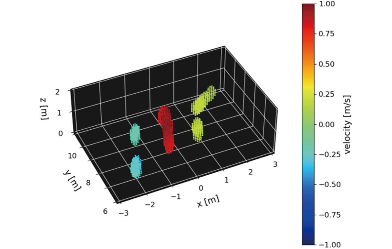
Consequently, from the point cloud position and the velocity information obtained from 3D imaging using the millimeter-wave radar, it is inferred that the three target objects equivalent to a height of about 1.6 m are moving at a speed of 1 m/s (about 3.6 km/h) or less, accordingly the targets are human beings walking. It is expected that it will be possible to identify the detected target objects and the status of them (walking statuses, such as walking and running and changes due to falls) through the observation of positional information (height and width), movement velocity, and the changes in point clouds due to temporal changes in these 3D spatial distributions.
In this study, as a basic verification to confirm the detection of point clouds of persons using 3D imaging, the millimeter-wave radar was set at 1.2 m, the height of human torso, assumed to be easy to obtain reflections from people. As a future subject, we would like to consider 3D imaging in situations where sensors are installed in high places and where they are expected to be used as an infrastructure sensor, multiple persons are included in the observation scene at various speeds (running, walking at low speed, riding a bicycle, etc.) and where not only persons but also vehicles and buildings are mixed in.
6. Conclusions
In this paper, a planar array antenna that could be realized under the single chip constraint was configured assuming the use of millimeter-wave radar as an infrastructure sensor, and verification experiments on 3D imaging of outdoor persons were conducted. Even with a small number of antennas of three transmitters and four receivers using a single chip, a large-aperture virtual planar array was realized by using the minimum redundancy arrangement, MIMO processing and KR product array processing, and the acquisition of point cloud information corresponding to the approximate human torso was verified using 3D imaging, although it was difficult to identify limbs. The results show that 3D imaging can improve the target object identification by using the altitude information of the point cloud compared to the conventional 2D imaging. A 3D imaging of three pedestrians was also conducted as an example of a multi-person observation scene, and it was confirmed that the approximate shape of each person (approximately 1.5 m apart) located at a distance of 8 to 10 m could be detected as a point cloud, and the possibility of state identification using the velocity information of the point cloud was demonstrated.
As a future subject, we will evaluate the performance of the radar by attaching it to a high place and conduct the observation under situations where objects with different RCS exist, such as observation scenes of multiple persons moving at various speeds (running, walking at low speed, riding a bicycle, etc.) that are possible on the street, and observation scenes when vehicles or buildings are located near the persons. In addition, we will conduct a study on target object tracking, and enhance the performance of target object positioning and identification of millimeter-wave radar through the studies for improving the state discrimination of individual target object by combining the temporal changes in the shape and motion line information of the point cloud.
References
- 1’╝ē
- Traffic Bureau/ Traffic Planning Division, ŌĆ£Number of Traffic Accident Fatalities in 2020,ŌĆØ National Police Agency, 2021-01-04, https://www8.cao.go.jp/koutu/kihon/keikaku11/senmon/k_4/pdf/s2.pdf (accessed March 12, 2021).
- 2’╝ē
- Central Conference on Traffic Safety Measures’╝ÄŌĆ£Basic Plan for Traffic Safety,ŌĆØ Cabinet Office, 2021-03-29, https://www8.cao.go.jp/koutu/kihon/keikaku11/pdf/kihon_keikaku.pdf (accessed April 2, 2021).
- 3’╝ē
- Public-Private Data Utilization Promotion Strategy Council, ŌĆ£Public-Private ITS Initiative / Roadmaps,ŌĆØ Cabinet Office, 2020-07-15, https://cio.go.jp/sites/default/files/uploads/documents/its_roadmap_2020.pdf (accessed March 16, 2021).
- 4’╝ē
- Y. Tanimoto, D. Ueno, and K. Saito, ŌĆ£Millimeter-Wave Traffic Monitoring Radar using High-Resolution Direction of Arrival Estimation,ŌĆØ OMRON TECHNICS, vol. 52, pp. 41-46, 2020.
- 5’╝ē
- Y. Tanimoto, S. Ohashi, and K. Saito, ŌĆ£Outdoor Human Detection by Millimeter-wave MIMO Radar with Minimum Redundancy Array,ŌĆØ in 2020 IEICE Communications Soc. Conf., 2020, p. 137, B-1-137.
- 6’╝ē
- A. T. Moffet, ŌĆ£Minimum-Redundancy Linear Arrays.ŌĆØ IEEE Trans., vol. AP-16, no. 2, pp. 172-175, 1968.
- 7’╝ē
- W. K. Ma, T. H. Hsieh, and C. Y. Chi, ŌĆ£DOA estimation of quasi-stationary signals with less sensors than sources and unknown spatial noise covariance: a khatri-rao subspace approach.ŌĆØ IEEE Trans., vol. SP-58, no. 4, pp. 2168-2180, 2010.
- 8’╝ē
- H. Yamada, ŌĆ£High-Resolution Imaging Techniques Using Millimeter-Wave Radar,ŌĆØ Trans. IEICE B., vol. J104-B, no. 2, pp. 66-82, 2021.
- 9’╝ē
- J. Li and P. Stoica, MIMO Radar Signal Processing. John Wiley & Sons, 2009, pp. 235-242.
The names of products in the text may be trademarks of each company.


