


Derivation of Arc Length Calculation for DC High Voltage Arc Interruption in Closed Space
- High capacity of relay
- Arc control
- Arc discharge phenomenon
- Arc interruption performance improvement
- Environmental energy management equipment
In recent years, the higher efficiency of systems has been promoted in renewable energy represented by photovoltaic power generation, which is increasingly used as a countermeasure against environmental problems. These systems consist of high voltage DC systems. The DC relays built into these systems for safety breakers must support higher voltages. In order to cut off a high-voltage arc with a DC relay, we need technology to control the arc generated when the arc is interrupted.
In this study, we tried to construct a relational expression between the arc length and the arc voltage when the arc was in contact with the resin in a closed space, such as a relay. The added parameters are the magnetic flux density that drives the arc and the distance that the arc abuts against the wall. By using the formula derived this time, it was possible to calculate the arc length required for arc interruption in a closed space with a load voltage of 800 V, and it was possible to realize interruption performance design with an appropriate arc length.
1. Introduction
The rise in awareness of environmental problems, such as global warming, is expanding the market of renewable energy using photovoltaic power generation and electric vehicles. Energy management devices and battery control circuits used for those are DC high voltage systems, and DC relays (hereafter referred to as relay) are used as safety equipment for emergency shutdown at the time of system trouble generation.
Vaporization of the bridge of molten metal produced between the contacts at the time of relay contact opening causes the dielectric breakdown between the contacts to generate an arc discharge (hereafter referred to as “arc”). The arc is a phenomenon where the temperature of a gas, such as air, rising to a temperature as high as several thousand degrees or more allows gas molecules to be ionized and decomposed to increase the electric conductivity of the gas and to allow electric current to flow in the gas. At this time, Joule heat generation by the electric current maintains the temperature of the arc conducting path to make the arc continue. Since the continuance of the arc makes the air surrounding the arc in the high temperature condition and burnout inside a housing and the wear of contacts occur1), the arc should be immediately interrupted.
In recent years, there is a tendency for the voltage of a system to be made higher for the purpose of reducing power transmission loss, and it is increasingly important to be capable of interrupting the arc safely and surely.
Generally, in order to interrupt the arc generated by the DC load voltage, it is necessary to increase the arc resistance and increase the arc voltage up to the load voltage2). Arc resistance has a positive correlation to arc length, and the longer the arc length, the higher the arc resistance. Therefore, interruption is difficult because higher voltage requires securing a longer arc length.
Experimentally obtained equation (1) is widely known that shows the relationship between the arc length required for the interruption and the load voltage3).

- L : Arc length [mm] E : Load voltage [V] I : Load current [A]
- Em : Minimum arc voltage [V] Im : Minimum arc current [A]
- K : 1.5×10⁻³ a : 3/2 b : 1/2
As shown in equation (1), when the load voltage and the current increase, the arc length required for the interruption is longer. In addition, the application range of equation (1) is up to 110 V for the load voltage and up to 50 A for the load current, and this relational expression can be applied when extending the arc only by the contact interval without utilizing the external magnetic field in an open space as in the atmosphere (hereafter referred to as “open space”).
As mentioned above, the higher voltage associated with the higher capacity of a system advances in recent years. Since a large contact interval cannot be secured because of the restriction of the relay in the space, such as a relay closed by resin (hereafter referred to as “closed space”), it is necessary to interrupt the load voltage of several hundred volts by driving the arc to extend it in the closed space utilizing an external magnetic field. Considering these, the calculation of the arc length in the relay design in the high voltage region requires the establishment of a relational expression corresponding to the following conditions to which equation (1) is outside the application:
- (i) Extension to high voltage region (100 V or more)
- (ii) Effect of external magnetic field application
- (iii) Effect of arc drive in closed space
Therefore, we approached this time to derive the relational expression between the arc length and the arc voltage when making the arc in contact with the resin by targeting the high voltage region as part of the study and driving the arc by the external magnetic field in the closed space.
This paper describes its approach in the following construction:
Chapter 2 describes the specimen relay and the method for experiments to verify the relationship between the arc length and the arc voltage.
Chapter 3 studies the relationship between the arc length and the arc voltage during the transient phenomenon, and studies the relationship between the arc length and the load voltage/current in the high voltage region while comparing it with equation (1). Then, we consider the effect of the external magnetic field, and finally, we describe the derivation process of the arc length calculation equation necessary for arc interruption when making the arc in contact with the resin in the closed space.
Chapter 4 describes the outcome as the results of reviewing this study, the remaining tasks, and future prospects.
2. Specimen relay and method for experiment
A schematic diagram of the specimen relay used for obtaining the relationship between the arc length and the arc voltage corresponding to the load is shown in Fig. 1.
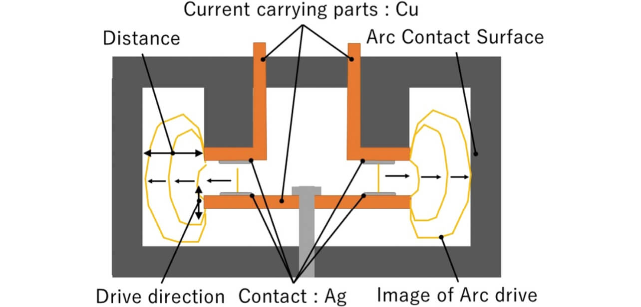
The relays used for the experiment have double-break contact construction consisting of two movable contacts and two fixed contacts, the contact material and the conductive part were decided to be silver (Ag) and copper (Cu), respectively, and the actuation direction of the contact was decided to be that shown in Fig. 1. Although not illustrated, when evaluating the effect of the external magnetic field, the field is added to all relays by a permanent magnet in the direction vertical to the paper face. When the external magnetic field is added, the arc generated at the time of the interruption is extended to the right and left direction of the paper by the permanent magnet to contact the inside of the housing. The part to which the arc contacts among the wall surfaces constituting the housing is called the arc contact face. In addition, in order to verify the effect of the collision of the arc to the resin on the relationship between the arc length and the arc voltage, construction was adopted where the distance between the terminal and the wall (hereafter referred to as distance between walls) could be changed.
The arc length was obtained from the actual arc image at the time of the load shutdown photographed using a high-speed camera. Fig. 2 shows an example of a high-speed camera image at the time of load shutdown.
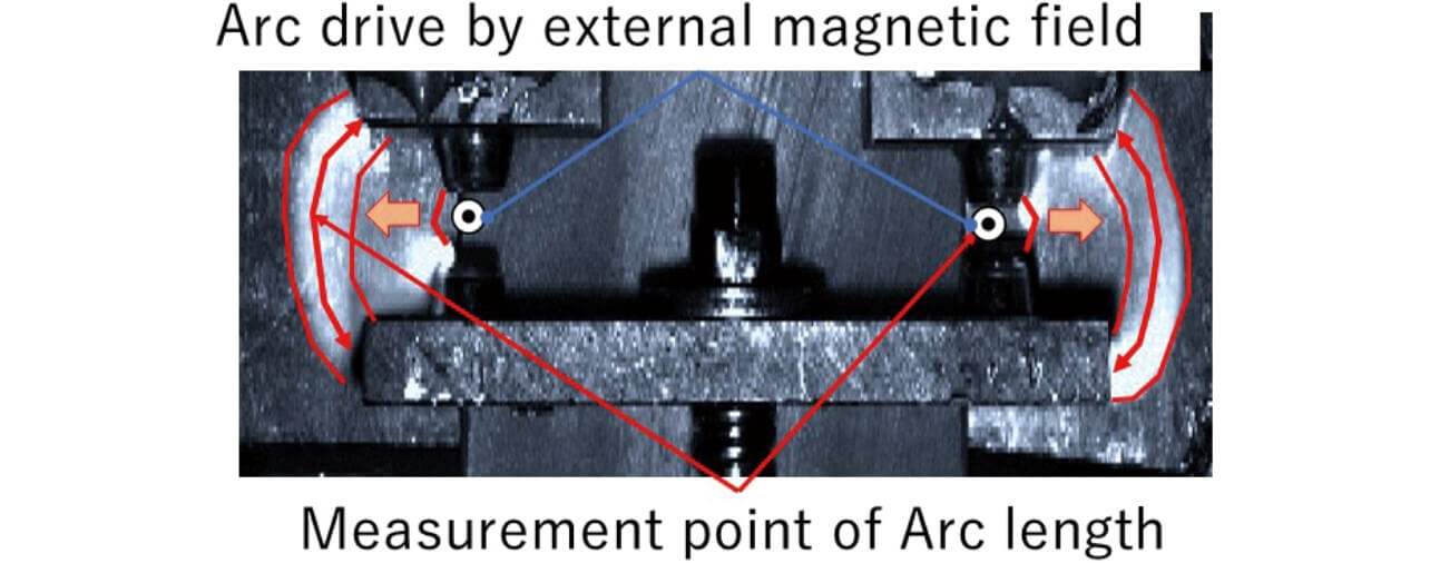
The path length in the center of the arc emission part on the image was assumed to be the arc length. In addition, the temporary change in the voltage between the contacts was simultaneously recorded as a voltage waveform. Fig. 3 shows an example of the temporary change of the arc voltage at the time of load shutdown.
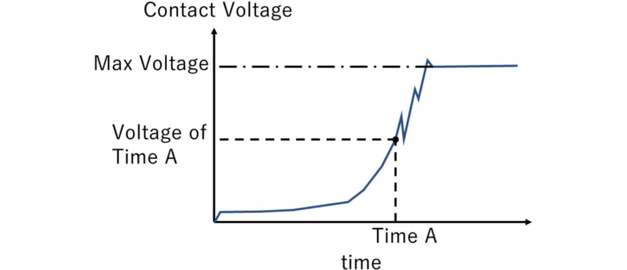
The arc voltage at the time when the image was photographed (Time A) was obtained from the arc voltage waveform as shown in Fig. 3. Although the equation (1) shows the relationship between the load voltage/current and the arc length at the time of the load shutdown, the relationship between the arc length and the arc voltage during the transient phenomenon of the load shutdown was measured in this experiment.
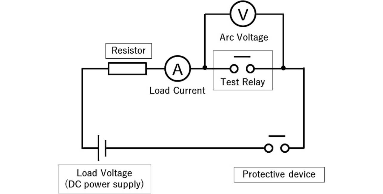
This experiment was conducted using the DC resistance circuit shown in Fig. 4, and the current to be electrified for the specimen relays and the voltage between the terminals of the specimen relays were measured.
3. Experiment results
3.1 Relationship between arc length and arc voltage during transient phenomenon
The relationship between the arc length and the arc voltage during the transient phenomenon when the load voltage was changed in the condition without adding the external magnetic field to the arc in the same load current is shown in Fig. 5.
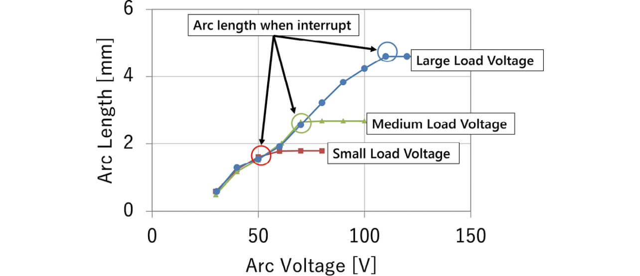
Assuming three conditions for the load voltage, each arc length was measured in the same arc voltage. The experiment results showed that the arc behavior during the transient phenomenon was constant regardless of the load voltage. In addition, it was verified that the arc length obtained from the arc voltage and the arc length obtained from the load voltage were almost the same. Therefore, the verification of the relationship between the arc length and the arc voltage during the transient phenomenon instead of verifying the load voltage made it possible to find an experimental equation concerning the load current, the arc length, and the load voltage. From the next subsection, we will verify the extendibility to the high voltage region by measuring the arc length and the arc voltage during the transient phenomenon, and we will establish the new relational expression corresponding to the effect of the application of the external magnetic field and the effect of the arc drive in the closed space.
3.2 Relationship between arc length and arc voltage during expansion of high voltage region
We will study the relation among the load current, the arc length and the arc voltage associated with higher voltage. The experiment was conducted in the condition without the addition of the external magnetic field by the permanent magnet using the relays shown in Fig. 1, and the arc transient phenomenon was measured at the shutdown of voltage of more than 100 V by changing the load current in two levels, high and low. The relations between the arc length and the arc voltage obtained from the experiment results are shown in Fig. 6. The dotted line in Fig. 6 shows the calculated values of the equation (1).
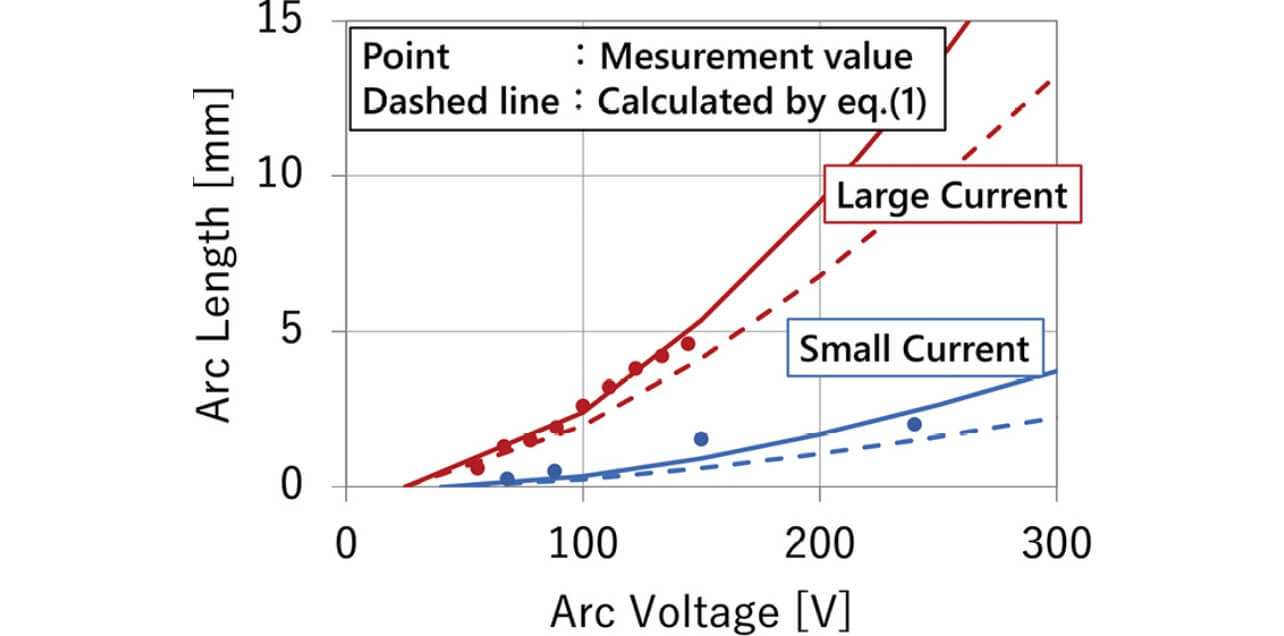
Fig. 6 allows verification that the calculated results by equation (1) and the measured values of the arc length deviate when the arc voltage exceeds 100 V, and the experiments this time showed that equation (1) cannot be applied in the range exceeding 100 V. On the other hand, it was verified that, when the current was higher, the arc length necessary for shutdown was longer similarly to equation (1). The relationship between the arc length and the arc voltage as the experiment results this time could be expressed by the following equation (2) when the load current was constant:

- L : Arc length [mm] Earc : Arc voltage [V]
- α and β : Coefficients
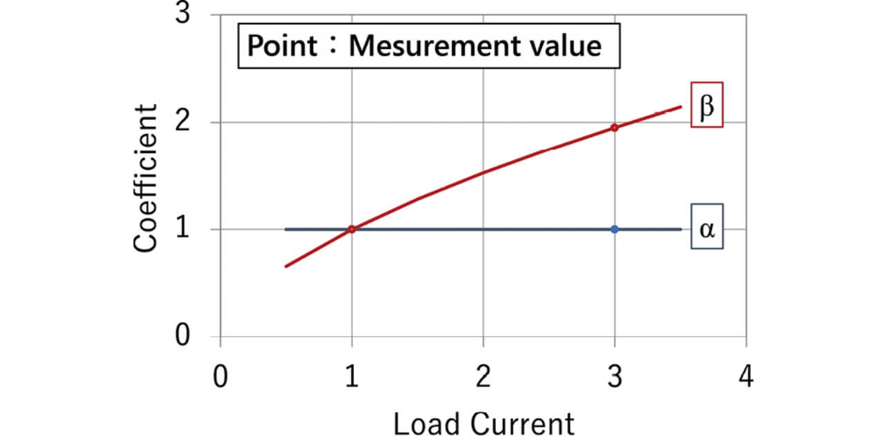
In addition, the relationship between the coefficients of α and β when the load current was changed is shown in Fig. 7, which is a graph normalized by assuming the minimum value of the load current in the experiment to be 1 and assuming each value of the coefficients to be 1. As shown in Fig. 7, since the coefficient α is constant regardless of the change of the load current and the coefficient β rises with the increase of the load current, they can be considered as a function of the load current.
Here, we defined the coefficient β as the function of the load current shown in the equation (3) similarly to the equation (1).

The equation (4) considering the change of the load current is derived by substituting the equation (3) for the equation (2).

I : Load current [A] K, α and b: Coefficients
Although it can be represented in the expression similar to the equation (1) even in the case of extending to the high voltage region as shown in equation (4), it was verified that the value of the coefficient was different. From the next subsection on, we will investigate the effect when the external magnet field is made to actuate to the arc, and the effect on each coefficient when the arc was made in contact with the wall using the equation (4) as a criterion to perform the formulation.
3.3 Relationship between arc length and arc voltage when external magnetic field added
The arc transient phenomenon was measured when the load voltage and current were made constant and when the arc was extended by the magnetic field generated and interrupted when a permanent magnet was externally arranged. The relationship between the arc length and the arc voltage when the external magnetic field was added is shown in Fig. 8.
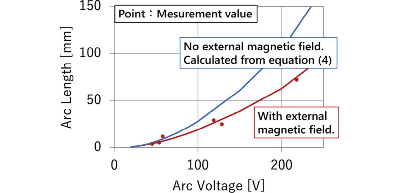
The experiment results using specimen relays for the case with the external magnetic field and the calculation results using the equation (4) for the case without the external magnetic field were plotted. Furthermore, the applied external magnetic field and the load current were made constant. It was found that the addition of the external magnetic field shortened the arc length in the same arc voltage in comparison with the condition without adding the magnetic field as shown in Fig. 8.
In addition, the tendencies of the coefficients of K and α when the external magnetic field was changed are shown in Fig. 9, which is the graph normalized by assuming the maximum value of the flux density to be 1 and assuming each coefficient value in case without the external magnetic field to be 1.
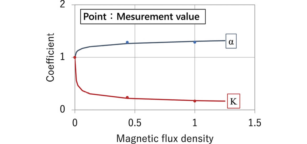
Since the increase in the magnetic flux density decreases the coefficient K and increases the coefficient α as shown in Fig. 9, they can be expressed by equations (5) and (6).


- B : Magnetic flux density [mT] e , f , g and h : Coefficients
- K0 and α0 : Initial values at B = 0
Equation (7) is obtained by substituting equations (5) and (6) for equation (4), the relational expression between the arc length and the arc voltage is derived considering the change of the load current and the effect of the magnetic flux density:

3.4 Relationship between arc length and arc voltage when utilizing resin
We will study the relationship between arc length and arc voltage at interruption when the load voltage and current were made constant and when the arc was extended by the external magnetic field generated when a permanent magnet was externally arranged and was made in contact with the wall. The experiment measured the arc transient phenomenon when the distance between walls was changed under the three conditions. The relationship between the arc length and the arc voltage when the arc was made in contact with the wall is shown in Fig. 10. The results of the measurement without the wall is the experiment result when the arc length and the arc voltage were measured until the arc was made in contact with the wall in the setting of each distance between walls. It was recognized that the contact of the arc with the wall as shown in Fig. 10 secured the arc voltage with the shorter arc length in comparison with the case without the wall. In addition, it was found that the shorter distance between walls secured the arc voltage with the shorter arc length.
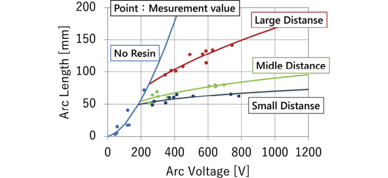
Fig. 11 shows the tendencies of the coefficients g and e when changing the distance between walls. Fig. 11 is the graph normalized by assuming the minimum distance between walls value at the experiment to be 1 and assuming each coefficient value at that time to be 1.
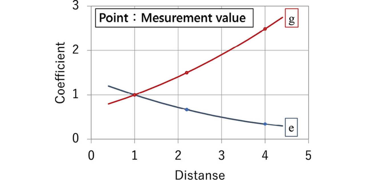
Since the increase in the distance between walls decreases the coefficient e and increases the coefficient g as shown in Fig. 11, the coefficients e and g can be expressed by the equations (8) and (9):


- d : Distance between walls [mm]
- j , k , m , n , o and p : Coefficients
Equations (10) and (11) are obtained by substituting equations (8) and (9) for equations (5) and (6). The relationship between the arc length and the arc voltage when adding the external magnetic field and making the arc in contact with the wall can be calculated from equations (4), (10), and (11):


In addition, Table 1 shows the meaning of each coefficient.
| Coefficient | Meaning |
|---|---|
| K | Coefficient representing sensitivity that the load current gives to arc length |
| j | Coefficient constituting coefficient K Represents the sensitivities of distance between walls (d ) and magnetic flux density (B ) |
| m | |
| n | |
| f | |
| α | Coefficient showing effect that the load voltage gives to arc length |
| o | Coefficient constituting coefficient α Represents the sensitivities of distance between walls (d ) and magnetic flux density (B ) |
| p | |
| q | |
| h | |
| b | Coefficient showing effect that the load current gives to arc length |
Examples of coefficients K and α when the magnetic flux densities of the equations (4), (10), and (11) are assumed to be constant and when the distance between walls was changed in the same load are shown in Table 2.
| Magnetic flux density | Constant value | |||
|---|---|---|---|---|
| Distance between walls *1 |
① | ② | ③ | Without wall |
| K | 0.9 | 0.6 | 0.3 | 1.4×10⁻³ |
| α | 0.2 | 0.3 | 0.5 | 1.6 |
The use of the wall as shown in Table 2 increases coefficient K and decreases coefficient α in comparison with the case without the wall.
This means that the effect of the arc voltage on the arc length necessary for the interruption when the arc is made in contact with the wall in the closed space decreases and the degree of effect of the load current on that increases.
It was verified that the design of the distance between walls was important in the condition where the arc was in contact with the resin wall in the closed space because the arc voltage for the same arc length rose when the distance between walls was reduced as shown in Fig. 10.
4. Conclusion
In recent years, it has been difficult to calculate the arc length necessary for the interruption using the experiment equation (1) calculated from the experiment results at the load voltage up to 110 V due to the higher voltage of systems. Therefore, this study attempted to establish the relationship between the arc length and the arc voltage when ① extending experiment equation (1) to the high voltage region,② considering the effect when allowing the external magnetic field to be actuated, and ③ making the arc in contact with the wall in the closed space targeting the DC voltage. The added parameter is the distance between walls when making the magnetic flux density for driving the arc and making the arc in contact with the resin. The application range of the load voltage is up to 200 V when not making the arc contact the wall and up to 800 V when making the arc contact the wall. The use of the equation derived this time enabled the calculation of the arc length necessary for the interruption of the arc in the closed space and the realization of the design of the interruption performance in the proper arc length.
This paper performed the studies by limiting the wall material with which the arc is made in contact to one type. Since the change of the arc-extinguishing performance by the wall material with which the arc is in contact is found in the reference literature4,5), we will hereafter advance the formulation of the relationship between the arc length and the arc voltage when the wall material is changed and will approach so as to enable a design that includes the optimization of the relay size.
We will contribute to the realization of the renewable energy society by advancing these approaches and enabling the product development of the optimized relay in order to safely and stably interrupt the arc in the high voltage region.
Reference
- 1)
- T. Morichi, H. Hama, S. Itoda, S. Tashiro, M. Tanaka, and A. B. Murphy, “Simulation technology for quantifying arc interruption phenomenon,” (in Japanese), OMRON TECHNICS, vol. 52, pp. 99-104, 2019.
- 2)
- Y. Moriguchi, H. Enomoto, R. Yamamoto, S. Fukuda, R. Ozaki, and Y. Ikeda, “Size reduction technology for high electric current main relay for EV and HEV,” (in Japanese), Panasonic Tech. J., vol. 61, no. 1, pp. 72-76, May 2015.
- 3)
- M. Sato, M. Hijikata, and I. Morimoto, “Disconnected arc of electric contact in atmosphere,” (in Japanese), J. Japan Inst. Met. Mater., vol. 36, pp. 238-247, 1972.
- 4)
- T. Onji, Y. Tanaka, and Y. Uesugi, “Effect of abrasion gas generated from polymer material on arc characteristic in current decay process.” (in Japanese), IEEJ Trans. Power Energy, vol. 131, no. 7, pp. 609-620.
- 5)
- D. Okazaki and M. Noda, “Performance evaluation of arc-extinguishing resin material in arc blow-out magnet mechanism.” (in Japanese), IEICE Tech. Rep., vol. 116, pp. 59-63, 2017.
The names of products in the text may be trademarks of each company.