


Method for Measuring Incremental Magnetic Permeability of Magnetic Materials and Construction of a DC Superposition Estimation Flow by Using It
- DC Superposition
- Minor Loop
- Magnetic field analysis
- Incremental Permeability
- Power Electronics
Magnetic materials like ferrite, which is used in power supply circuits that handle high currents, such as DC/DC converters, exhibit a rapid decrease in inductance due to the influence of the magnetic flux generated as the DC current component increases. This phenomenon is called DC superposition, and it has a negative impact on the efficiency of electrical energy conversion. There has been a need for a property prediction technique to determine the current limit value prior to design.
The Play Model is well known as a mathematical model that can accurately represent this phenomenon1). However, the poor availability of the model, the difficulty of making actual measurements for the model, and the large computational load have become bottlenecks when trying to perform the analysis in reality.
In this study, we investigated an alternative method that uses the slope of the minor loop, called incremental permeability. Although this method limits the superimposed current to a sinusoidal wave, it has a feature of light computational load, and by deriving the material constants using a combination of actual measurement and analyses using a toroidal core, it can be evaluated more quickly and accurately than the play model method. Because of this advantage, a practical application study was conducted.
As a result, we were able to obtain the expected results with a light computational load of only a few tens of minutes and an estimation error of less than 5%, and we were able to make a prospect for practical application. In this paper, we report on the practicality of the method through a concrete example.
1. Introduction
Advanced power electronics technology for the efficient operation of increasingly higher-current electric energy has become a requirement in recent years. Demand has been intensifying for smaller-size power supplies with lower losses. Naturally, the resulting trend is toward switching devices with higher frequencies. However, the magnetic saturation properties specific to the magnetic materials contained in magnetic devices used as critical power supply components limit the maximum current, which pose a significant challenge. The DC superposition property is one of the main properties affected by magnetic saturation. When a direct electric current causes a magnetic flux in and around a magnetic material, the magnetic material exhibits a rapid drop in inductance as it approaches magnetic saturation. This phenomenon negatively affects the ripple current and the load response properties during power supply operation and may result in a malfunction. Thus, importance is attached to technologies that allow the accurate estimation of limits for direct electric currents.
Some power supply designers have begun attempts at estimating the DC superposition property using magnetic field analysis. Widely used are permeability  = B0 /H0 (where B0 is the magnetic flux density B at the point P in Fig. 1 and H0 is the magnetic field H at the point P) and differential permeability
  = dB /dH. However, their use is known to cause errors due to their principles2). The factors responsible for these errors cannot be resolved without an analysis that takes into account hysteresis properties, which are also the factor responsible for the minor loop in Fig. 1.
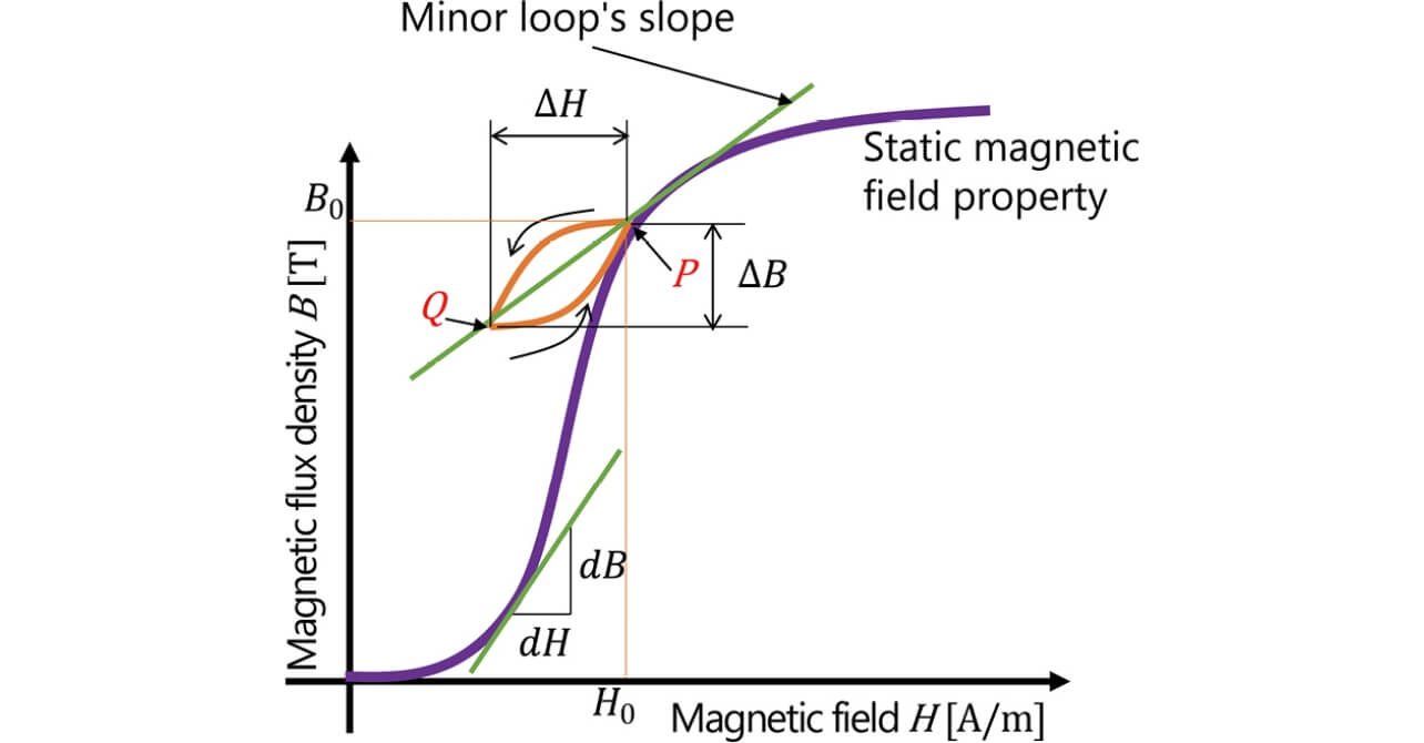
 = ΔB /ΔH : incremental permeability
- = B0 / H0 : permeability
- = dB /dH : differential permeability
- P and Q : minor loop’s branch points
Included among the models proposed to simulate any hysteresis property is one called the Play Model1). This model is a mathematical model that simulates the magnetic properties as a set of symmetric loops as in Fig. 2. This mathematical model is expressed by Equation (1):

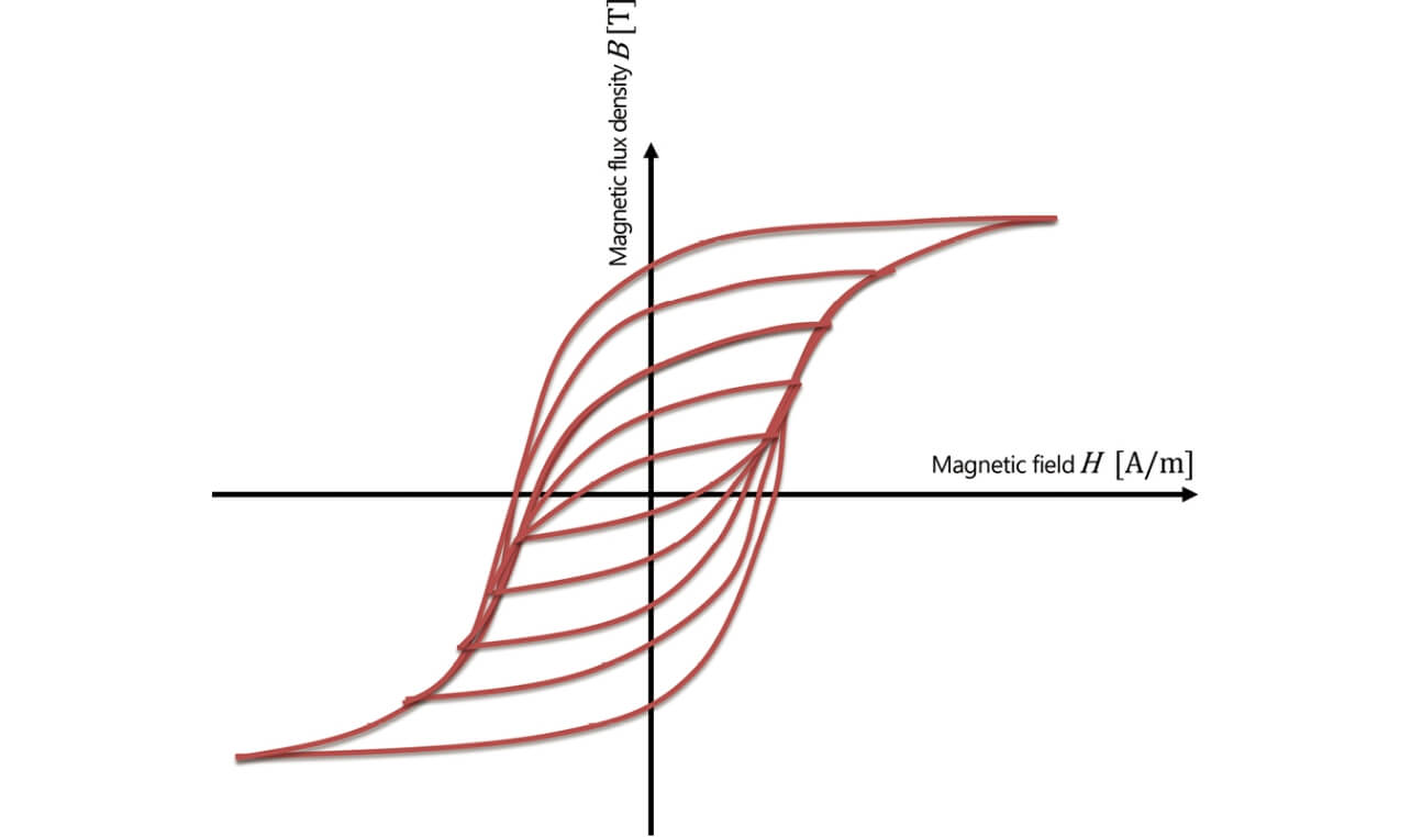
where Pξm is a function representing a hysteresis behavior called a hysteron and fm is a function representing the shape of hysteresis loops, which are constituted into an aggregate of an m number of loops with different amplitudes.
In practice, however, Play Models are difficult to use due to the following challenges:
- ① Material constants are not readily available and must be determined using such methods as measurement.
- ② The measurement of high-frequency hysteresis loops close to a saturation region requires special equipment or measurement techniques.
- ③ Because the magnetic properties are handled as loops, the computational load increases at higher frequencies of the superposed alternating current.
Some authors propose methods that limit superposed alternating electric currents to sinusoidal waveform currents with a constant amplitude to address these challenges3),4). In these methods, the ΔB and ΔH of the minor loop in Fig. 1 are uniquely determined relative to the static property B0, so that this property can be expressed only by their ratio, i.e., . This defined by Equation (2) is specifically called the incremental permeability:

However, as with the Play Model, these methods require their users to obtain by measurement because is usually not included among published material properties. Unlike the Play Model, these methods have the advantage of allowing a relatively straightforward measurement of : they only require the superposition of a small-amplitude current on a direct electric current without the need to drive high frequency high current for high-frequency regions, and especially ones with a magnetic flux density close to that of the saturation region.
Hence, in the present paper, we present a method that can easily measure the incremental permeability with high accuracy and the flow of a DC superposition property estimation process developed based on this measurement method. In addition, we report how our measurement method ensures the practical coincidence between measured and estimated values with a sufficiently light computational load.
2. Principle of the simulation
2.1 What are minor loops?
The typical magnetic material’s B-H property, expressed as static magnetic field characteristics, as shown in Fig. 1, is used as the material constant in conventional simulations of direct and alternating currents. Assuming the cause of inductance variation in a device, such as a power inductor, the present study considers a state where a direct electric current is continuously applied as a bias current besides a superposed high-frequency current. In the meantime, a change is underway inside the magnetic material in which the direct electric current generates a static magnetic field, which, by turn, causes a magnetic flux (point P in Fig. 1), around which occurs the vibration of a small magnetic field generated by the high-frequency current represented as the P → Q and Q → P curve in Fig. 1. This vibration does not occur along the B-H curves in the static magnetic field but, rather, causes the formation of a minute loop sloped differently. This minute loop is called a minor loop. This minor loop slope, in other words, the incremental permeability , is reflected in the inductance value during the DC superposition state. Therefore, a mechanism must be developed to detect and incorporate into simulations.
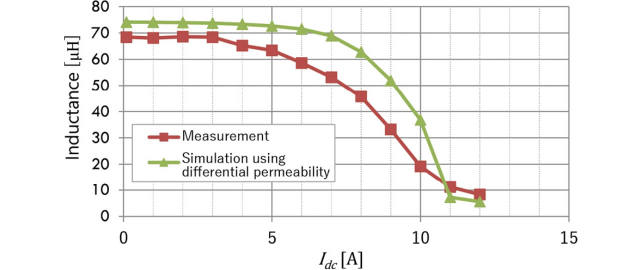
2.2 Cause of the error in the B-H property-based simulation
For the inductance properties during a state with a high-frequency current of 100 kHz superposed on a direct electric current, a simulation was performed using the B-H curve’s differential permeability, which is a static property. Fig. 3 compares the obtained simulation results with the corresponding measurement results and illustrates the occurrence of a considerable direct electric current error of approximately 2 A. This error occurred, probably because the minor loop’s slope was affected by the frequency and static magnetic field of the superposed current, which caused the difference between the B-H curve’s slope and the minor loop’s slope to become too large to ignore.
What is important to resolve the error is to perform a magnetic flux calculation for a simulation reflecting the material property (). Then, high-accuracy estimation results are obtained, which allow the accurate determination of the material’s inductance variation. The next and subsequent subsections regard as an important constant and describe in detail the steps from measured value determination to incorporation into the simulation.
2.3 CAE-based estimation method
The flow of analysis is as follows:
- ① Derive the distribution of the direct electric current-induced static magnetic field using the B-H property
- ② Convert the static magnetic field distribution into an incremental permeability distribution using the B- property
- ③ From the incremental permeability distribution, derive the inductance of the magnetic field induced by the high-frequency current
This time, we used JSOL’s JMAG-Designer as the magnetic field analysis tool. This tool functions to define the relationship of the specific permeability  to the magnetic flux density B as one of the magnetic properties besides the constant specific permeability and the non-linear B-H property. The specific permeability was defined as the incremental permeability , together with the combined use of the B - material data with the B-H property, to establish an estimation method based on the flow of the above series of steps.
2.4 Material constant determination by measurement
This subsection considers the means of measuring the property as the key for prediction. As generally expressed by Equation (3), is the function of the high-frequency current frequency f , high frequency-field amplitude ΔB, and the static magnetic field B. We specified the superposed high-frequency current as a sinusoidal waveform current with a constant frequency to exclude f and ΔB from the variables. In this way, we pursued a method that guarantees accuracy with a low analysis load, albeit within limited conditions.

As regards the measurement, we prepared dedicated magnetic parts for measurement to make it easy to execute the measurements necessary to calculate the incremental permeability .
3.  calculation method based on the combination of measurement and simulation
3.1 Overall flow of DC superposition property analysis
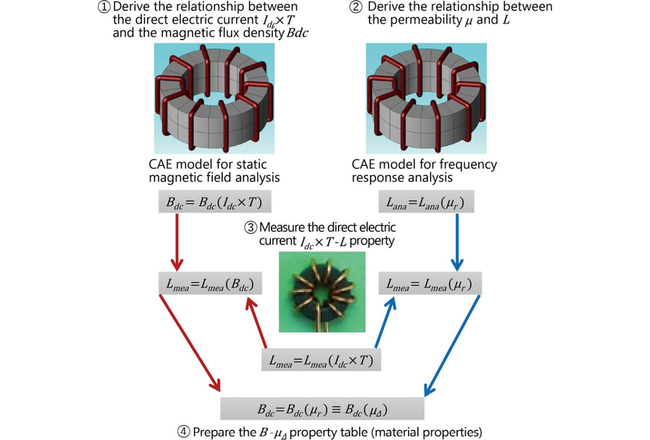
Fig. 4 shows the overall flow of the DC superposition property analysis performed this time for general magnetic parts, such as smoothing chokes. In Fig. 4, the material constant B - derivation part shows the flow of determining the material constant of a magnetic material.
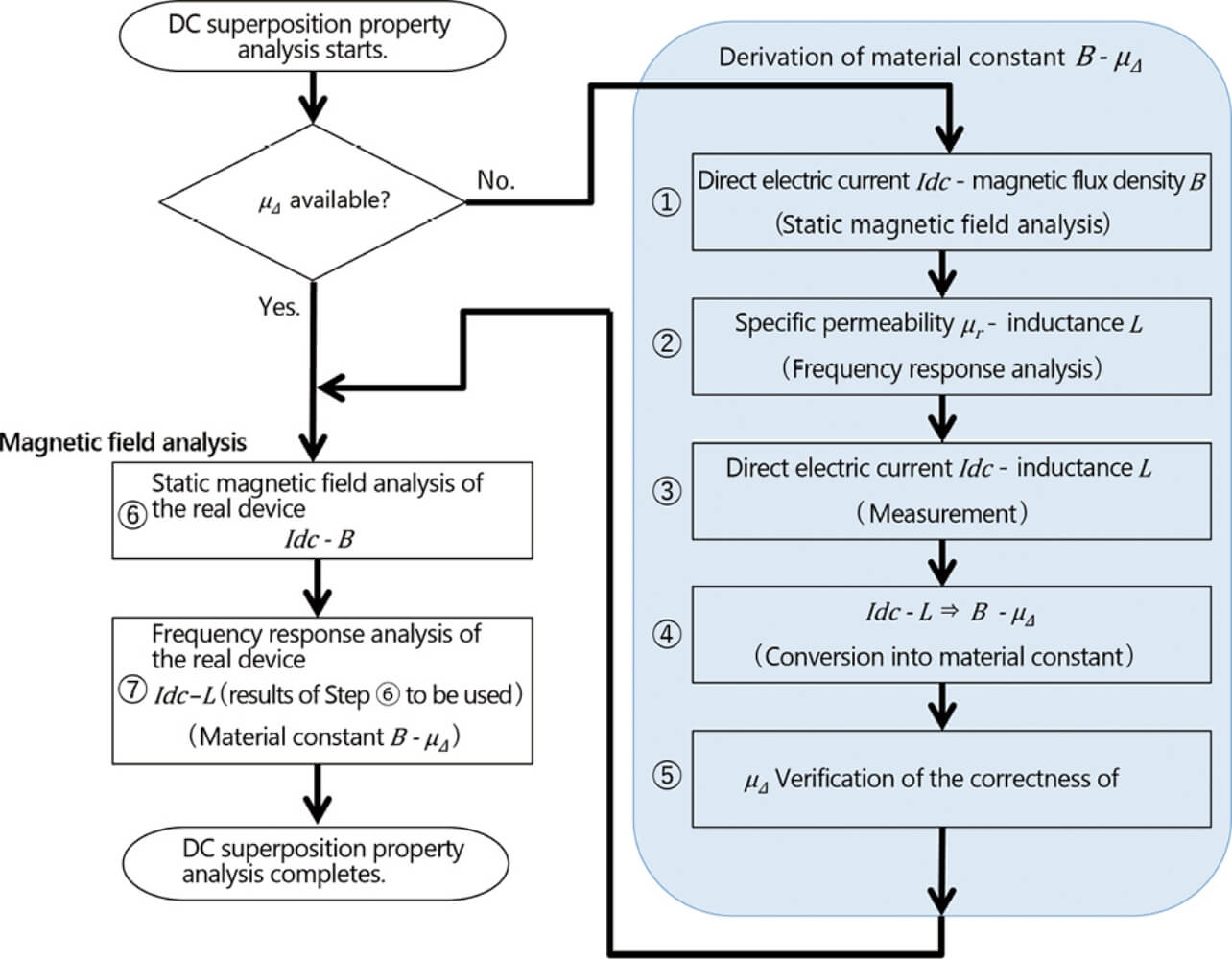
Fig. 5 is a relational diagram of the steps in the material constant B - derivation part. The following subsections each describe in detail one of the study items according to the flow shown in Fig. 5.
 property derivation steps
3.2 Derivation of the relationship between the direct electric current  and the average magnetic flux density
  (Step ① in Fig. 5)
The magnetic flux inside the toroidal coil core can be estimated using an approximate expression even when considerations must extend to the magnetic saturation region. The method used for this purpose employs a non-linear function that approximates the B-H property to extend considerations to non-linear magnetic properties5).
This time, a simulation was used to achieve high accuracy for the heterogeneity of the cross-sectional magnetic flux density between the inner and outer diameters and the properties near the core’s magnetic properties’ saturation region.
The first thing to consider for confirming the saturation properties is the model of a direct electric current flowing through the toroidal core. Step ① in Fig. 5 is the modeled form of the toroidal coil used at Step ③ for measurement. The material’s B-H magnetic property is applied to this model to perform static magnetic field analysis to simulate the relationship between the coil current  ×
×  and the average magnetic flux density
  (Fig. 6), where is the direct electric current and is the number of coil turns. is the averaged value of the toroidal coil’s cross-sectional magnetic flux density. Thus, Step ① first confirms that the magnetic saturation properties are obtained as static properties.
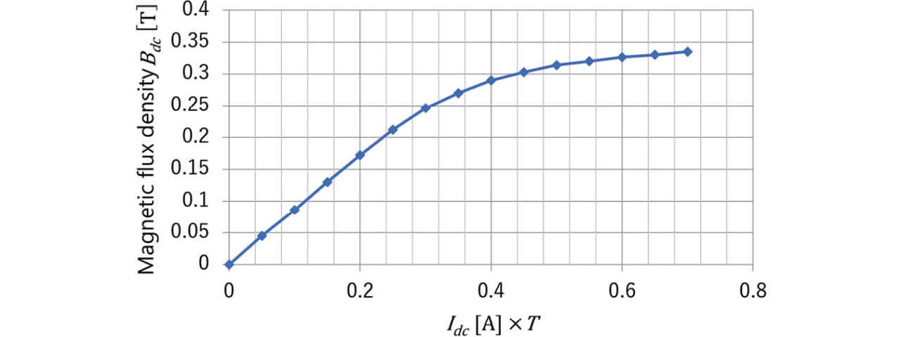
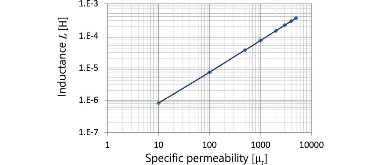
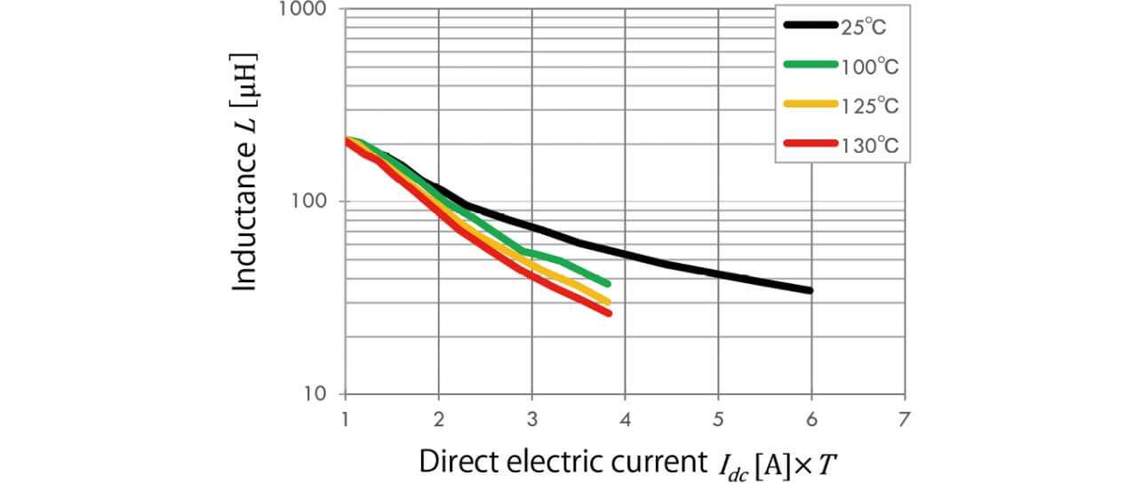
Fig. 7 is a graph of the relationship between the specific permeability and the inductance L obtained by frequency response analysis from the same toroidal core model according to the flow shown at Step ② in Fig. 5.
3.3 AT-L property measurement by the toroidal coil (Step ③ in Fig. 5)
Fig. 8 shows the external appearance of the measurement equipment used this time. This equipment consisted of a combination of an LCR meter and a DC source unit to allow the DC superposition property measurement, including temperature properties.
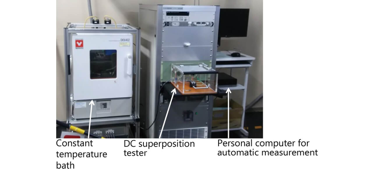
Fig. 9 shows a graph of the relationship between the direct electric current × and the inductance L in a real toroidal coil shown in Fig. 5- ③ as determined by the measurement using the equipment shown in Fig. 8. The high-frequency current superposed on the direct electric current was specified equivalent to the high-frequency current of the real magnetic part of our evaluation interest to ensure the coincidence between their property values.
3.4 Conversion of the - property into a material constant (Step ④ in Fig. 5)
Obtained by the simulation and measurement in Subsections 3.2 and 3.3, respectively, are two relationships expressed as = ( × ) and  = () and another relationship expressed as
  = ( × ), where the inductance values, and , are obtained by simulation and measurement, respectively. Then, the two relational equations obtained as a result of the simulation are used to convert and × into and , respectively, to obtain the relationship expressed as = () (Fig. 10).
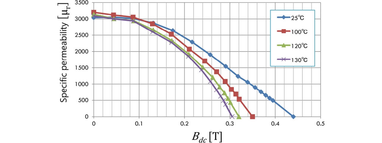 - relationship (incremental permeability )
Fig. 10 shows that the specific permeability received by the superposed alternating electric current decreases under the influence of the magnetic flux density due to the direct current. In other words, it represents the minor loop slope shown in Fig. 1. This series of processes can redefine as (incremental permeability), which means that the - relationship has been obtained.
3.5 Verification of by reanalysis (Step ⑤ in Fig. 4)
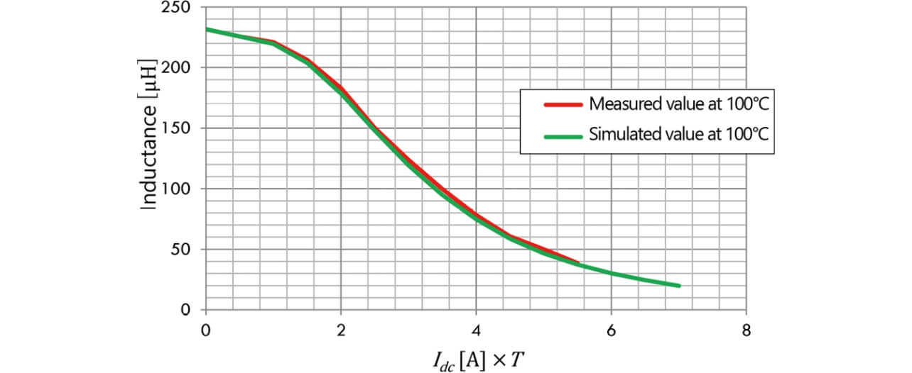
To verify the B - property obtained in Subsection 3.4, we applied the obtained B - to our model to verify the simulation reproducibility of the relationship between × and L. Fig. 11 is a graph comparing the measured and simulated values obtained with the temperature condition set to 100°C. The error is within 5%, which indicates the reproducibility with sufficiently high accuracy. Thus, the incremental permeability derivation method described above and the simulation method based thereon have been verified as effective.
4. Analysis case of smoothing choke’s DC superposition property
4.1 - property derivation using the core material of a smoothing choke
This section presents a case of applying the measurement and simulation methods using the toroidal core described in Section 3 to the DC superposition property analysis of a smoothing choke, a type of magnetic part used for DC/DC converters. Fig. 12 shows the B - property calculated from the combined results of the measurement and simulation of the DC superposition property of a toroidal core manufactured using the same core material as used in the smoothing choke.
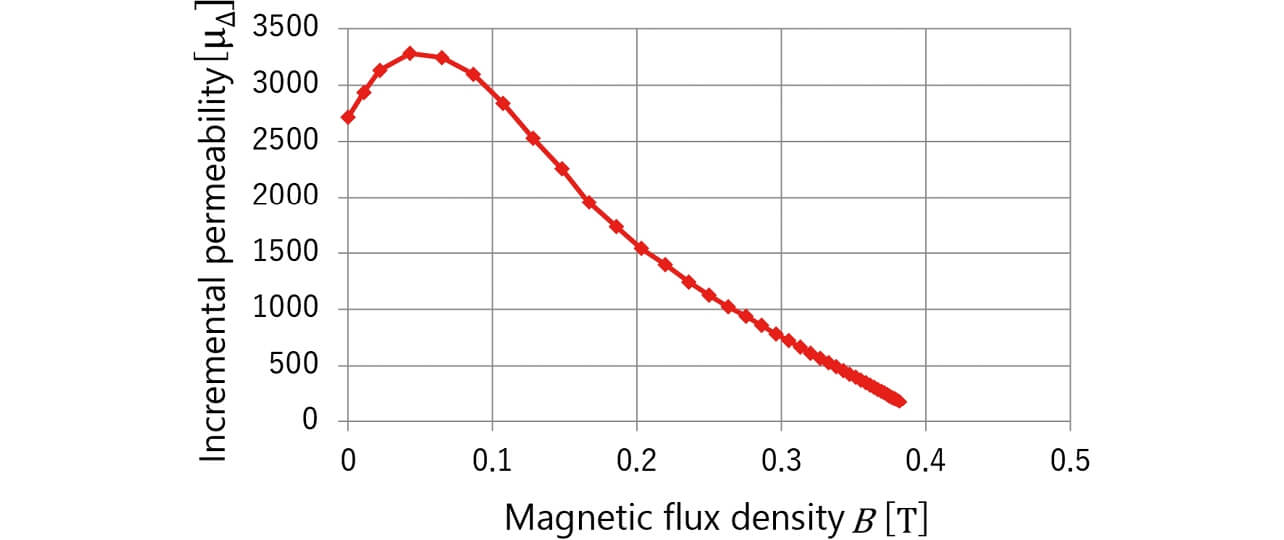 property established using a toroidal core
4.2 Analysis flow for the smoothing choke
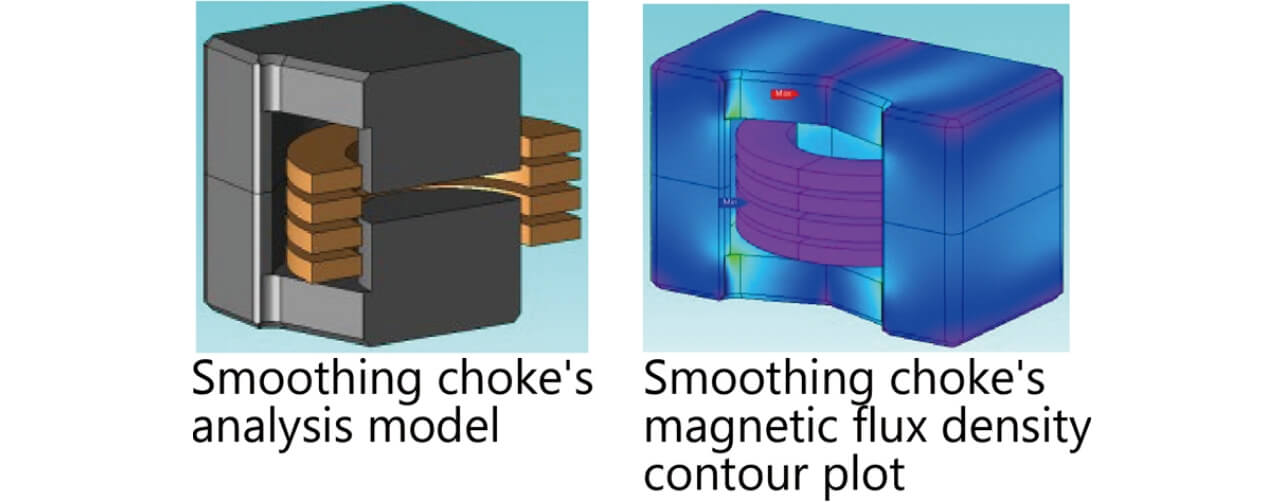
Fig. 13 shows the magnetic field analysis model of the smoothing choke and the magnetic flux density contour plot of the frequency response analysis results. For this model, a DC superposition analysis was performed according to the following steps:
- ① Apply the ferrite core’s B-H non-linear static properties to the core material to perform a DC static magnetic field analysis on the smoothing choke model (Step ⑥ in Fig. 4).
- ② Using the same model, set the core’s internal magnetic flux density distribution data, which are the analysis results obtained in Step ①, as the initial magnetic flux distribution in the new model to simulate the magnetic flux distribution during a DC-energized state. Switch the core’s magnetic property to the B - property obtained in Subsection 4.1. Using a frequency response analysis, flow the high-frequency current superposed during the smoothing choke’s energized state to determine the inductance L derived from the B - property (Step ⑦ in Fig. 4).
- ③ Prepare the results of sweeping the direct electric current in Step ① from 0 to the max current and apply the analysis in Step ② to each result to determine the DC superposition property.
4.3 Comparison of the DC superposition analysis results and the measurement results for the smoothing choke
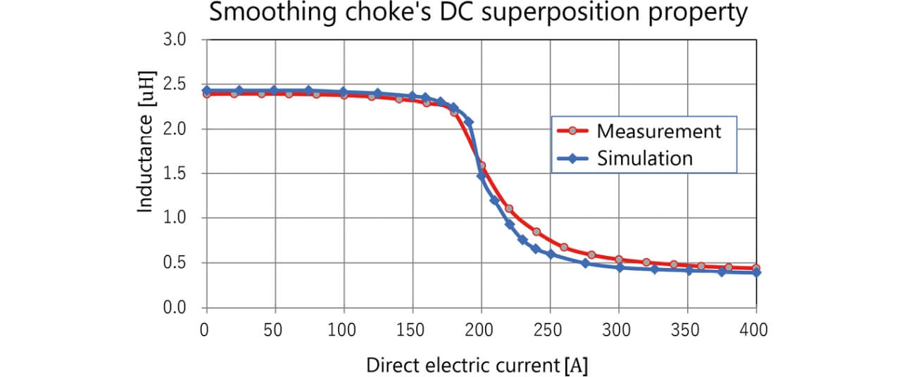
Fig. 14 shows the results of the measurement and simulation of the DC superposition property. The measurement results are the smoothing choke’s DC superposition property values obtained using the measurement equipment shown in Fig. 8. A look at the 1.5 H inductance point as the inflection point for the inductance confirms that the measurement and simulation results coincide with each other within an error of 5% for the direct electric current value of 200 A and are sufficiently practical.
5. Conclusions
A means of conversion into material constants using a minor loop slope can be established as a solution to the demand for a method of readily estimating with high accuracy the DC superposition property of increasingly higher-current, higher-frequency magnetic parts. The present study confirmed that a smoothing choke’s property prediction using this method serves as a means of DC superposition property derivation with a low computational load and sufficiently high accuracy. To give a practical form to the solution, we developed a DC superposition property estimation method by combining a measurement method for converting confidential incremental permeability into a material constant with high accuracy and two different analysis methods using the material constant.
For the future, we propose to deploy this technology to power supply design products using power electronics and incorporate it into the standard design process for products critically dependent on the DC superposition property. In addition, accommodate to further increases in the amplitude and frequency of superposition currents, we will develop a technology for converting the material constant - into a multi-variable function, including amplitude and frequency.
References
- 1)
- T. Matsuo and M. Shimasaki, “An identification method of play model with input-dependent shape function,” IEEE Trans. Mag., vol. 41, no. 10, pp. 3112-3114, 2005.
- 2)
- S. Higuchi, Y. Takahashi, K. Fujiwara, N. Yamada, N. Nishida, and K. Takai, “Analysis of DC-biased characteristics of reactor for power conditioner considering magnetic hysteresis property,” (in Japanese), IEEJ Tech. Meet. Handout, Jan. 23, 2014, pp. 19-24.
- 3)
- K. Hashimoto, Y. Takahashi, K. Fujiwara et al., “Study of measurement method of magnetic property of magnetic materials for reactor,” (in Japanese), IEICE Tech. Rep., vol. 111, no. 400, pp. 91-96, 2012.
- 4)
- K. Ueda, “DC superposition characteristic measurement of reactors and comparison with the measured values,” (in Japanese), JMAG User Conf., 2011.
- 5)
- IEEJ Magnetics Committee (ed.), Magnetics — Fundamentals and Applications —, Rev. ed. Tokyo: Corona Publishing Co., Ltd. (in Japanese), 2013, 272p.
The names of products in the text may be trademarks of each company.