


Development for On-site Customization Technology on Facial Image Sensing
- Facial Image Sensing
- On-site Customization
- Machine Learning Algorithm
- Data Collection System
- Driver Monitoring
We propose a novel method for on-site software customization to improve performance of facial image sensing.
In cases that a user has the following facial characteristics, it is difficult to perform facial image sensing with high accuracy:
- Big scars on the face
- Defects, deformations of the facial parts such as eyes, nose, and mouth
According to our approach, only setting some simple parameters is needed, on the other hand, no relearning process on facial feature values is needed. So, it brings high performance of facial image sensing, as well as general. Also, we show how to collect the intended user’s facial images for software customization and its accuracy validation by using portable and user-friendly equipment. We have confirmed the effectiveness of our proposed method by the experiments using actual facial images.
1. Introduction
The facial image sensing technology that detects human faces from images and estimates face orientations, eye open/closed states, gaze lines, etc., has played an important role in improving peopleʼs convenience in various fields, including the face autofocus function of digital cameras or human-subject scene extraction from surveillance video footage taken by video monitoring systems1).
In recent years, facial image sensing technology has been becoming increasingly commonplace in practical applications in various industries, such as driver monitoring systems installed in vehicles by the automotive industry2) or elderly monitoring services provided by the life service industry3). Expectations are running higher and higher for facial image sensing technology as a technology that will provide safety and security to many more people.
For such expectations to be met, it is critical to perform accurate sensing for individual users without dependence on them. In some cases, facial image sensing may, however, become difficult to perform with high accuracy because of significant differences that occur during facial image processing between the values of facial features extracted from an image and those of learned facial features to be referring to and such cases include faces with large scars from injury or any other cause; faces with any of its organs, such as eyes, nose, or mouth, partially lost, or heavily deformed; or faces with its organs shifted from their supposed average positions due to causes such as congenital diseases (Table 1).
During, for example, driver monitoring, such faces may affect the accuracy of the determination of the driverʼs state (e.g., distracted or drowsy), resulting in failure to ensure the safety and security of the user. Besides facial image sensing, there are alternative driverʼs state estimation methods based on indirect information such as the driving histories of individual drivers4). The alternative methods, however, do not perform direct sensing of face orientations or eye open/closed states but perform indirect estimation based on history information. With such methods, emergency responses would be difficult.
Therefore, customization becomes necessary to ensure accurate facial image sensing of the intended users. It is, however, undesirable to ask the user to visit any of the manufacturerʼs offices or factories: some users may feel it too burdensome to do so. This is why on-site customization at locations such as dealer shops matters. This paper proposes a method for realizing this customization.
| Type | Example |
|---|---|
| Large facial scars | Large scars, burns, and surgical wounds |
| Facial organ defects or deformities | (Continuous) use of an eyepatch, post-fracture deformity, etc. |
| Disarrangement of facial organs | Treacher-Collins syndrome |
2. Outline of our facial image sensing technology
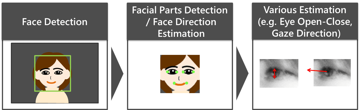
Fig. 1 shows the flow of our facial image sensing technology. A face region is detected from a still or video image. Next, upon the detection of facial organ feature points (e.g., endpoints of the eyes, nose, or mouth), their relative positions are used to estimate the face orientation angles. Then, various estimation processes are performed based on the detected feature points. For example, the eye open/closed state or the gaze line is estimated from the image information of the areas near the eye feature points.
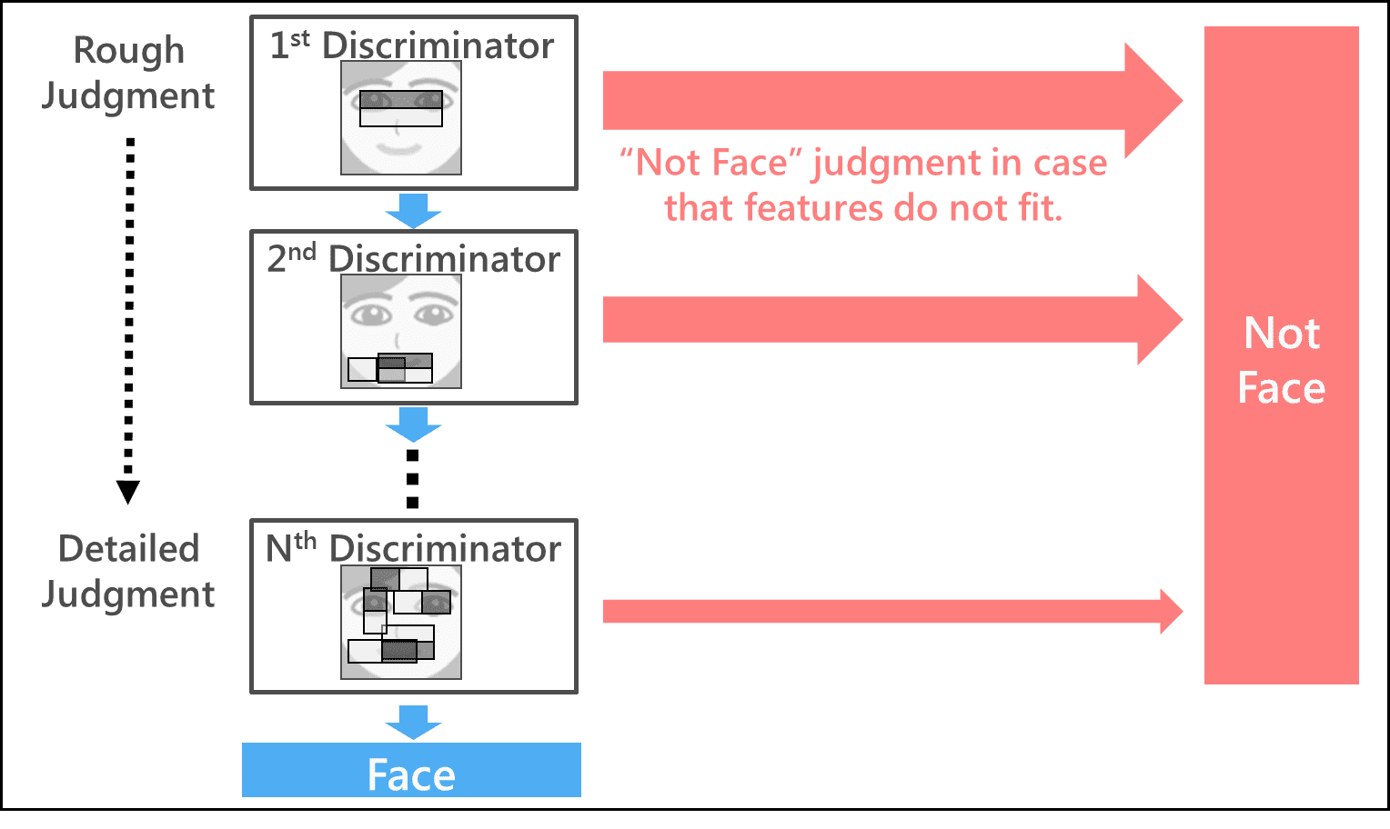
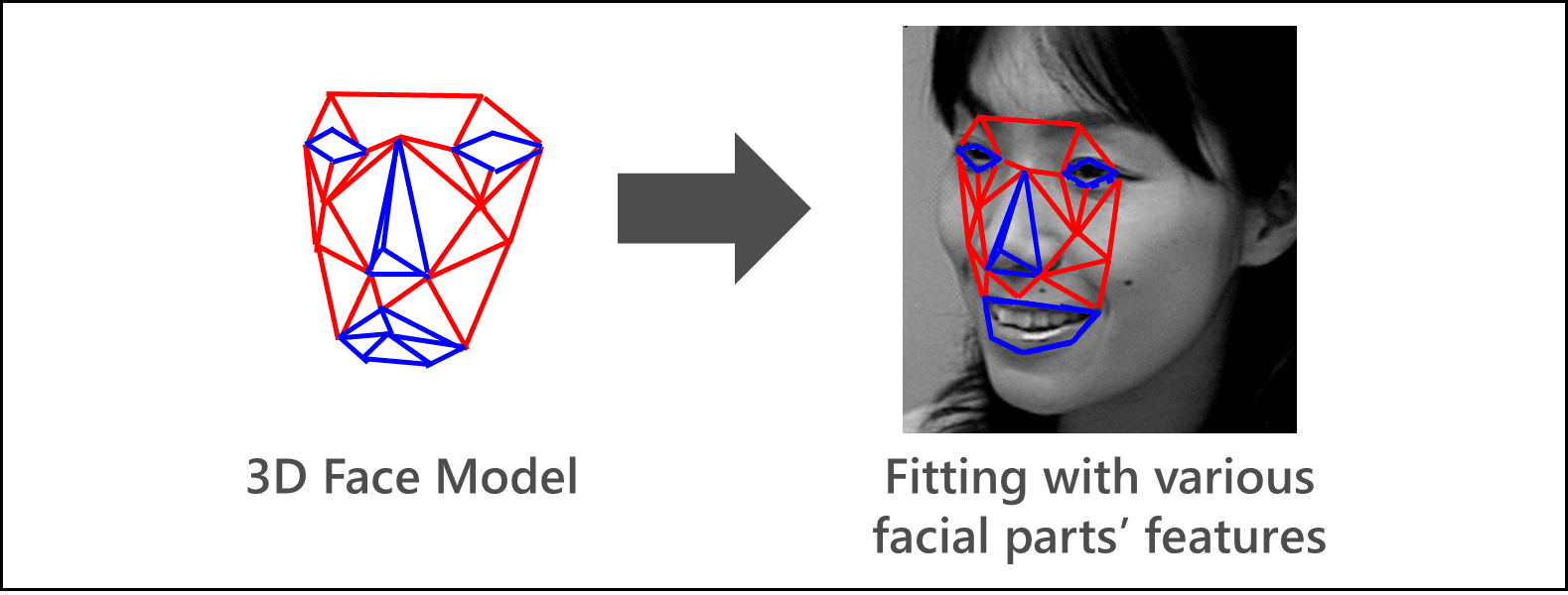
The advantage of our facial image sensing lies in that it works in real time with high accuracy even on embedded devices/systems equipped with extremely low-performance memory or CPU, thanks to a small, fast proprietary algorithm (small in the amounts of information and computation required for processing). Let us see some examples. In face detection, as shown in Fig. 2, feature value-driven face/non-face judgment based on the differences in brightness and darkness between partial regions of the face proceeds stepwise in a hierarchy of processing steps from a coarse processing step with a light load to more detailed processing steps and excludes obvious non-face regions accounting for the most area of the image from candidates at earlier stages to allow real-time processing1). Additionally, in facial parts detection/face orientation estimation, real-time processing is made possible by another proprietary technology that takes advantage of regression operations to perform high-speed fitting of a 3D face model compatible with various faces to 2D facial images5) (Fig. 3).
3. Challenges to the realization of on-site customization
The following two points pose major challenges to the realization of on-site customization of facial image sensing:
3.1 Easy-to-customize algorithm
Attention must be paid to the following points when customizing facial image sensing for intended users:
- Should relearning add any change to the existing learned facial feature values referring to during facial image processing, a face initially sensed with high accuracy may become unable to be sensed.
- The addition of an algorithm specially designed for intended user sensing will make the processing time required for sensing two times as long. Moreover, the development of additional source codes and the subsequent quality assurance will take many person-hours and development costs as needed.
For these reasons, an algorithm under consideration must be such that relies only on simple parameter setting to allow accurate sensing of the intended users while maintaining the original accuracy and processing speed.
3.2 Collection of facial image data for customization
On-site collection of facial image data of the intended user is required for the following purposes:
- Performing customization
- Validating whether face detection, face orientation estimation, and other face sensing-related operations performed with high accuracy as a result of the customization
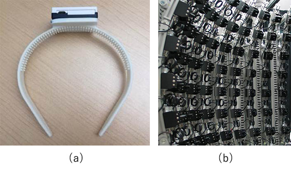
For the validation of the estimated face orientation, it is of particular importance to obtain facial image data containing the known true values of face orientation angles. The methods available for this purpose include the use of an acceleration (gyro) sensor6) or that of a multi-angle imaging system consisting of more than one camera (Fig. 4). The former, however, involves a sensor to be worn on a body part, such as the head, and hence may feel loathsome or burdensome to the intended user. Meanwhile, the latter is an impractical option in that the equipment is too bulky to carry into space-tight locations such as dealer shops. The method under consideration must be one such that uses user-friendly, on-site portable equipment to collect facial image data containing the known true values of face orientation angles with a minimum burden on the intended user.
4. Our proposed method
4.1 Easy-to-customize algorithm
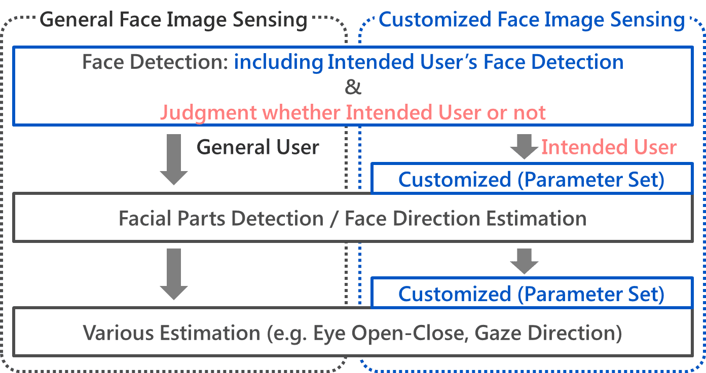
Fig. 5 shows the flow of our proposed method. The remaining parts of this paper describe in sequence two components of particular importance in facial image sensing: face detection and facial parts detection/face orientation estimation.
4.1.1 Face detection
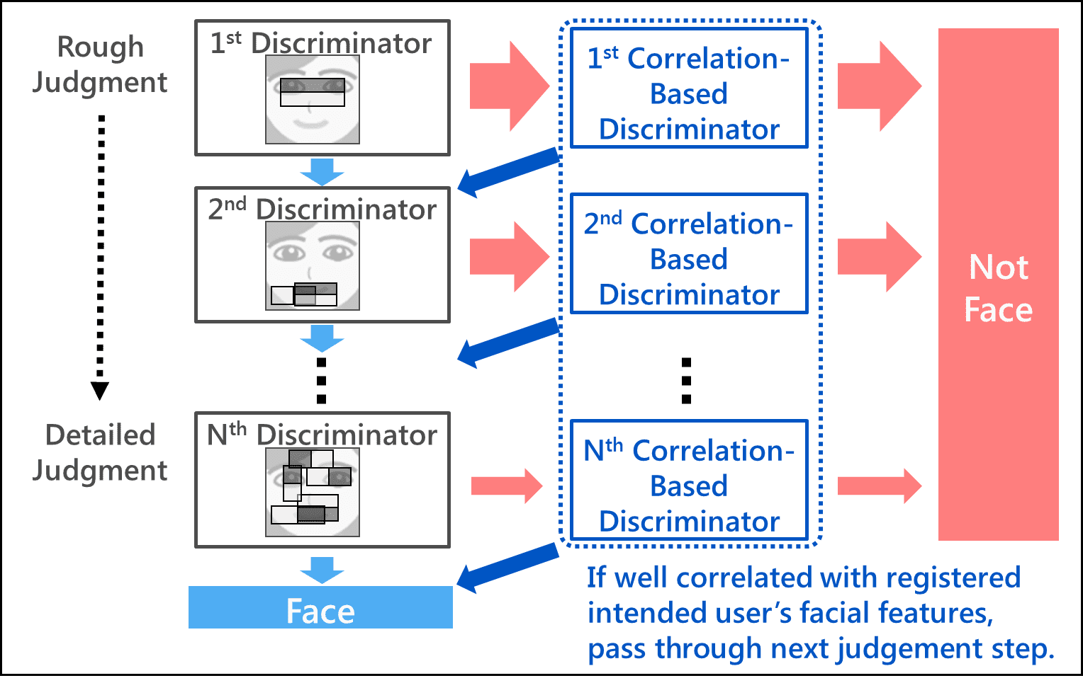
Fig. 6 shows the outline of the algorithm. This algorithm consists of the conventional face detection discriminator in which the facial feature values of the intended user needing customized image sensing are registered layer by layer, as shown in Fig. 2, and a process that checks the correlation with the registered feature values. Similar to before, feature values based on the differences in brightness and darkness between partial regions of the face are extracted from the input image so that the hierarchically structured face detection discriminator will perform face/non-face discrimination. Even if a non-face judgment occurs at one of the layers of this process, the next layer of the process will start without excluding the potential “non-face” from the “face” candidates, as long as the feature values extracted from the potential non-face image has a high correlation with the intended userʼs facial feature values registered in advance. In this way, the intended user face will be detected with high accuracy at all the layers without being judged as a non-face. Besides, a face detected initially with high accuracy will undergo the conventional discrimination process by the face detection discriminator, whereby the original level of accuracy will be retained.
The only parameter setting that this algorithm requires is the addition of feature values extracted from one or several intended user facial images. The algorithm requires no relearning of previously learned feature values. Moreover, the amount of computation required for the newly added correlation computation flow is 10 or more times smaller than that required for feature value extraction from an image or for face/non-face discrimination by the discriminator. Thus, the real-time aspect of the face detection process can be maintained
In this face detection process, as can be seen from the flow shown in Fig. 5, a face will be judged as the intended userʼs face if well correlated with the registered feature values of the latter. After that, the algorithm will perform various estimations, such as facial parts detection/face orientation estimation, eye open/closed state estimation, and gaze line estimation, for the intended user needing customized image sensing. Conversely, for a face with a low correlation, the algorithm will perform conventional facial parts detection/face orientation estimation, eye open/closed state estimation, gaze line estimation, etc.
4.1.2 Facial parts detection/face orientation estimation
As explained above, our method of facial parts detection/face orientation estimation is based on 3D face model fitting. The reason that the facial part detection/face orientation estimation is difficult in cases like those listed in Table 1 is considered that fitting is difficult because this face model fails to conform to a specific part of a facial organ of the intended user. For example, when a white eyepatch is worn continuously over the right eye, the right-eye portion of the model will end up erroneously fitted to an area other than the right-eye area, resulting in a poor fitting of the whole face model. Hence, a possible solution may be to perform the fitting without using the feature values of that specific facial part. The fewer number of available feature points will, however, make the fitting process less stable.
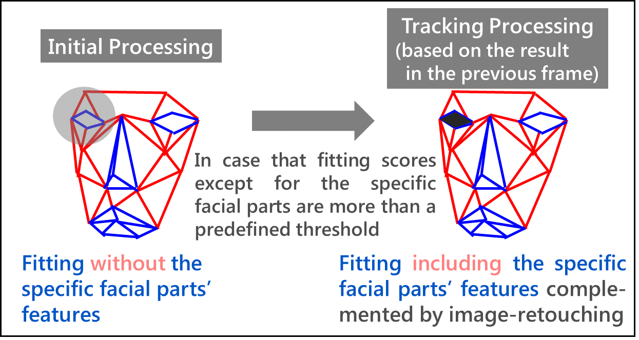
Then, we propose the algorithm shown in Fig. 7. At first, this algorithm performs 3D face model fitting without using the feature values of a specific facial part. If the reliability of the fitting of all facial parts other than the specific facial part reaches or exceeds a prescribed threshold, it will be assumed that the entire face, including the specific facial part, has been fitted with high accuracy. From the subsequent frame on, a transition to such a processing mode based on the previous frame results, as described below, will occur for an enhanced stability.
First, the location of the specific facial part on the image is estimated from the fitting results of the previous frame, followed by image processing to complement the feature values. This takes advantage of the characteristics of 15- to 30-frame-per-second video footages in which the movement of the location of each facial organ point per frame can be deemed as negligibly small. If, for example, the specific facial part is the right eye, the location of the right eye on the image will be estimated from the fitting results of the previous frame, followed by image processing that paints the location black like the pupil of an eye for feature value extraction. This allows the use of the conventional 3D face model-based fitting method (in which the feature values of a specific facial part are also used), thereby enabling stable, high-accuracy facial parts detection and face orientation estimation.
The only parameter setting that this algorithm requires is the registration of the specific facial part of the intended user. The algorithm requires no relearning of the original 3D face model. Moreover, the newly added processing is only the image processing of a limited, small area of a specific facial part. Thus, the real-time aspect of this process can be maintained.
4.2 Collection of facial image data for customization
Fig. 8 shows a typical configuration of the data collection system. The intended user is asked to change the face orientation gradually in the vertical and horizontal directions (approximately by 5 to 10 degrees each time), so that the following paired data can be obtained in sequence from the same viewpoint with an image capturing device capable of obtaining range (depth) images and 2D images from the same viewpoint, such as a time-of-flight (TOF) camera:
- Range (depth) image data of the intended user
- 2D facial image data of the intended user
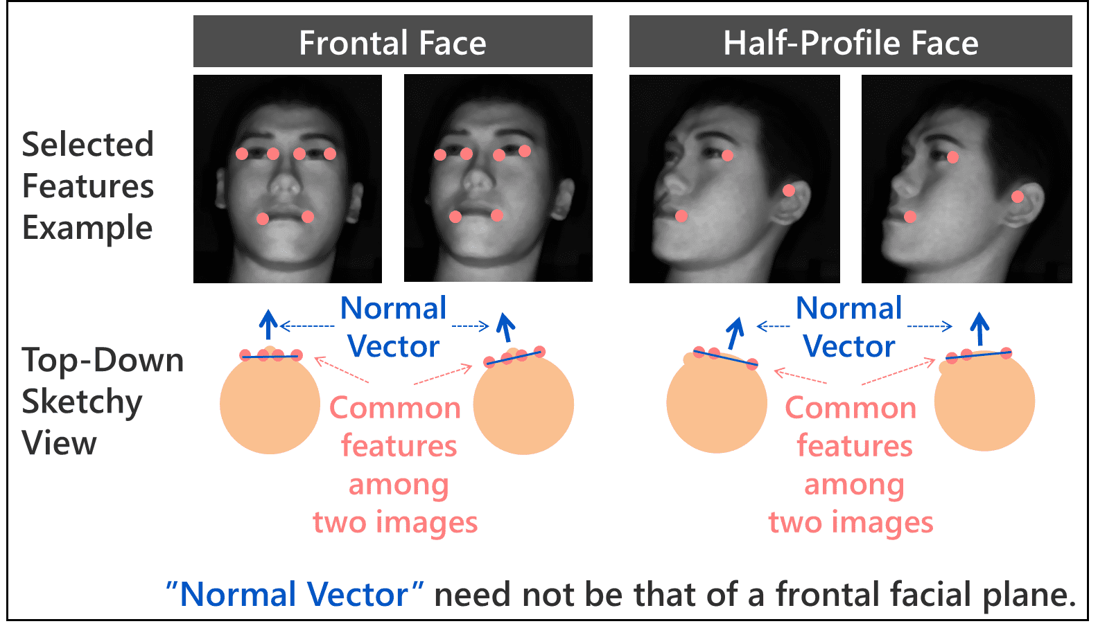
Then, the 3D position data of the facial organ feature points (e.g., endpoints of the eyes, nose, mouth, and ears) available from the obtained paired data are used to calculate the true values of face orientation angles in each 2D facial image data. First, the reference image and its face orientation angles are determined. For example, when the relative positions of the camera (sensor) and the user in an assumed application are right opposite to each other, a random frontal face image is selected as the reference image. Then, its face orientation angles are defined as the zero-degree yaw angle (horizontal angle of the face orientation) and the zero-degree pitch angle (vertical angle of the face orientation). Next, as shown in Fig. 9, common feature points at three or more random points in two images similar in face orientation angles to each other are associated with each other by template matching to calculate the normal vector relative to a plane consisting of these feature points (that does not have to be the same as the face orientation plane), in other words, the relative face orientation angles, by the least-squares method. After that, the true values of face orientation angles in each 2D facial image data can be calculated in sequence by repeating this relative face orientation angle calculation process while changing images one after another. It should be noted here that the two images similar in face orientation angles to each other may differ in common feature points from each other depending on the face orientation. In a frontal face image, for instance, the eyes and the mouth will be the common feature points. In a half-profile face, however, one eye becomes less visually accessible; hence, along with the other eye and the mouth, the ears, for example, will become common feature points. In this way, the feature points will be switched as appropriate for the face orientation to calculate the true values of face orientation angles.
Our proposed method allows a single-camera system configuration for easy portability to the site. Besides, this method requires the intended user only to change face orientation during the image capturing process and allows acquisition of facial image data containing the true values of face orientation angles with the burden on the intended user reduced to the very minimum.

5. Experiment
This chapter describes an experiment conducted to evaluate the effectiveness of our proposed method of on-site customization of facial image sensing. This experiment assumed driver monitoring as the intended application. A simulation of monitoring the user from an oblique direction with a camera installed at the center of the dashboard of a vehicle was performed using a face orientation angle image with a right yaw angle of 25° and an upward pitch angle of 10° as the reference image for true value derivation.
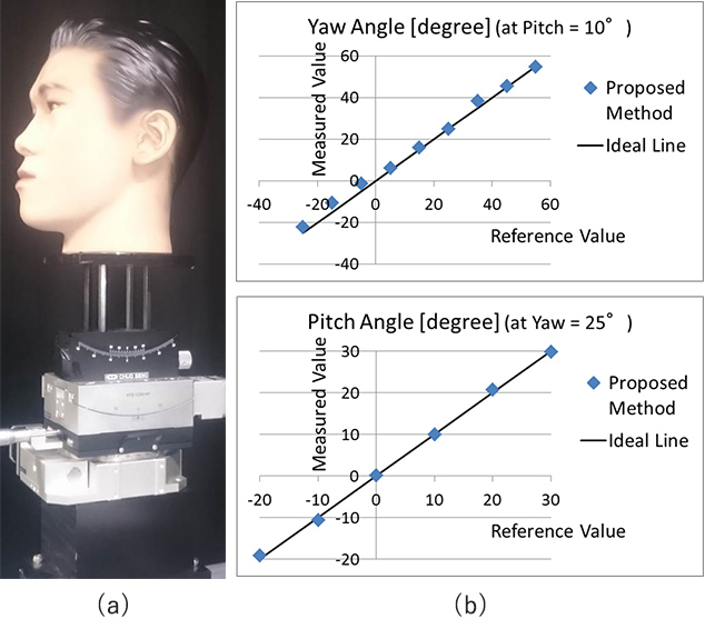
5.1 Evaluation of true value derivation
First, an experiment was performed using a dummy to evaluate whether the true values of face orientation angles could be derived with high accuracy from paired data (range (depth) and 2D facial images) obtained on-site for an intended user. As shown in Fig. 10(a), the dummy head installed on a high-precision, multi-axial stage was set up in the userʼs position on ʻthe data collection system configuration shown in Fig. 8. Then, while the face orientation angles of the dummy were changed vertically and horizontally in 10-degree increments, paired data were obtained to calculate the face orientation angles in each 2D facial image according to our proposed method. After then, the respective calculated face orientation angles were compared with the angles of the high-precision stage.
Fig. 10(b) shows the experimental results. The horizontal axis of the chart represents the reference value (high-precision stageʼs angle); its vertical axis represents the measured value (calculated face orientation angles). Both the pitch angle and yaw angle values are plotted close to the ideal 45-degree inclination represented in thin line, indicating that the face orientation angles were calculated with high accuracy.
The results of the above experiment confirmed the effectiveness of referring to face orientation angles calculated by our proposed method as true values for use in customization results validation.
5.2 Evaluation of the effectiveness of customization
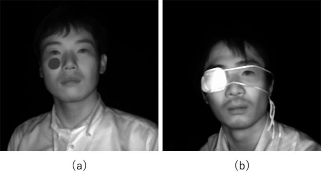
Second, our proposed method of customization was applied to actual persons in two experimental cases in Fig. 11 to evaluate the possibility of enhancing the accuracy of face detection or face orientation estimation. Case A subject was one with a large facial scar, while Case B subject was one with a defect of a facial organ. The former test subject had a 3 cm diameter gray color label (Munsell color label) affixed immediately below the right eye to simulate a large scar. The latter test subject wore an eyepatch over the right eye.
In the experiment, the test subjects changed their face orientation gradually in vertical and horizontal directions in front of a camera; during this time, video footages of the two subjects were recorded as the source data of paired range (depth) and 2D facial images. Then, from the video footages, paired-data still images were extracted in approximately 10-degree increments of face orientation angles to calculate the face orientation angles in each 2D facial image similar to the experiment in Section 5.1; for this experiment, these values were specified as the true values of face orientation angles. Then, customization (parameter setting) was performed according to our proposed method. More specifically, the feature values for face detection were extracted from one to several 2D facial images and registered, followed by registration of the specific facial part for facial parts detection/ face orientation estimation. In both cases of this experiment, the feature values for face detection were extracted from a frontal face image and a half-profile face image and registered. Additionally, the right eye was registered as a specific facial part. Finally, 2D facial image data extracted from paired-data video footages were used to obtain the face orientation angles by our proposed method of facial image sensing for comparison with the true values of face orientation angles mentioned above. It is the prerequisite for accurate face orientation angle estimation that the preceding face detection process is performed with high accuracy. Therefore, as regards this experiment, the evaluation of the face detection results is subsumed under the comparative evaluation of the face orientation angles. The goal aimed at was to estimate the face orientation angles within errors of ±5°.
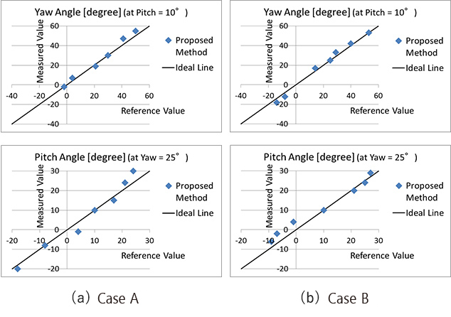
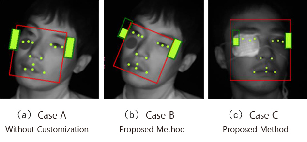
Fig. 12 shows the experimental results. The horizontal axis of the chart represents the true values of face orientation angles, while its vertical axis represents the measured value. Meanwhile, Fig. 13 shows typical results of facial image sensing; in each photo, the red frame represents the face detection results, the round yellow dots represent the facial parts detection results, and the two yellow rectangles jointly represent the estimated degree of eye opening/closure.
In Case A without customization, the fitting near the right eye showed a tendency of shifting due to the influence of the large scar, as shown in Fig. 13(a). This problem was improved by our proposed method as shown in Fig. 13(b). As a result, the face orientation angles were estimated with high accuracy as shown in Fig. 12(a) that plots the measurement points for both the pitch and yaw angles within errors of ±5° from the ideal 45-degree inclination represented in thin line. Meanwhile, in Case B, where without customization, face detection failed because of an eyepatch, our proposed method improved the problem, enabling the detection of the eye-patched face as shown in Fig. 13(c). Moreover, the face orientation angles were estimated within errors of ±5° as shown in Fig. 12(b).
The above results confirm the effectiveness of the on-site customization of the facial image sensing method proposed herein.
6. Conclusions
This paper has presented an on-site customization method that provides high accuracy to face detection, face orientation estimation, and other face sensing-related operations for users with difficulties for facial image sensing due to large facial scars or defects or deformities of facial organs, such as the eyes, nose, or mouth.
This paper has confirmed that our proposed method can, without requiring anything more than simple parameter settings, provide high accuracy to the facial image sensing of the intended users needing customized image sensing and to validate reliably the accuracy of, for example, the face orientation estimation involved in that process. Additionally, we established a method that uses user-friendly, on-site portable equipment to collect facial image data necessary for parameter setting and validation without imposing a large burden on the intended user.
The remaining challenges include the following:
- Improved stability: Stable detection/estimation of, for example, facial organ points or face orientations regardless of various actions of the intended user needing customized image sensing (e.g., face scratching or continuous covering of a facial part, such as the nose or mouth, with a hand)
- Enhanced robustness: Necessary when the facial appearance of the intended user needing customized image sensing differs (e.g., because of the use of a mask or a pair of sunglasses) significantly from when on-site facial image data was collected
- Improved reliability of accuracy validation: Necessary when feature points are difficult to extract (e.g., with ears hidden by hairs) during the process of deriving the measured data to be referring to as true values
We will make improvements in these challenges and deploy the technology presented herein horizontally to various fields, including fatigue degree detection for factory workers or human state sensing for health care purposes, in addition to driver monitoring.
References
- 1)
- I. Fumikazu, T. Takuya, E. Shinji, and Y. Masashi, “Hardwarization of Face Detection Technology” (in Japanese), OMRON TECHNICS, Vol. 158, pp. 90-94, 2007.
- 2)
- H. Tadashi, K. Koichi, A. Hatsumi, H. Hideto, Y. Takayoshi, F. Hironobu et al., “Time-series Deep Learning-based Estimation of Acceptable Level for Return to Driverʼs Seat” (in Japanese), in Proc, Meeting on Image Recognition and Understanding (MIRU), 2016, No. PS1-63.
- 3)
- OMRON Corporation, “Monitoring Camera Sensor ʻKazoku Mesen (Familyʼs Gaze)ʼ” (in Japanese), https://plus-sensing.omron.co.jp/kazoku-mesen/(accessed Nov. 1, 2019).
- 4)
- Panasonic Intellectual Property Management Co., Ltd., “Information Processing System, Information Processing Method, and Program”, Japanese Unexamined Patent Application Publication No. 2018-97804. 2018-06-21.
- 5)
- K. Koichi, K. Yoshinori, S. Lao, and K. Masato, “Facial Feature Point Detection/Head Attitude Estimation by Fast 3D Model Fitting” (in Japanese), in Proc. Meeting on Image Recognition and Understanding (MIRU), 2008, pp. 1324-1329.
- 6)
- U. Naoko, Z. Hu, and Y. Dong, “Face Orientation Detection with a Single Depth Camera” (in Japanese), IPSJ SIG Technical Report, Vol.2014-MBL-73, No. 18/Vol. 2014-ITS-59, No. 18, 2014.
Written consent to the use of images was obtained for all facial images presented herein.
The names of products in the text may be trademarks of each company.