


Millimeter-Wave Traffic Monitoring Radar using High-Resolution Direction of Arrival Estimation
- Millimeter-wave Radar
- Automated Drive
- Driving Safety Support Systems
- Antenna Control
- Direction of Arrival Estimation
Driving safety support and automated driving technology have attracted much attention for realization of a safe transportation society. Infrastructure coordinate system is expected to play an important role in complex traffic scenes at intersections and junctions because infrastructure sensors can complement information from sensors installed in vehicles. Research and development are underway to put these technologies into practical use.
We are developing millimeter-wave radar as an infrastructure sensor that can be expected to offer robust detection performance regardless of the surrounding environment. Millimeter-wave radar tends to suffer from lower angular resolution due to the lack of the number of antennas compared to an optical sensor. This will make detection and separation of a vehicle running on the adjacent lane side by side very difficult. To overcome this problem, we introduce the Direction of Arrival (DOA) estimation with high angular resolution to millimeter-wave radar and evaluated the performance of angular resolution through a field experiment. As a result, it was confirmed that a vehicle running on the adjacent lane side by side can be detected and the effectiveness of DOA estimation was verified.
1. Introduction
The Japanese government has set the numerical target of reducing the annual national traffic death toll to less than 2,500 persons per year by 20201). While the national traffic death toll has been decreasing year by year, the rate of this decrease has leveled off in recent years2). Besides, many other traffic-related social issues have emerged, such as heavy traffic jams mainly in urban areas, economic losses resulting therefrom, and shortage of drivers in distribution and transportation services.
To solve these issues and realize a safe, secure, and comfortable traffic society, various research and development projects are underway for safe driving support systems and automated driving technologies. For instance, in the Strategic Innovation Creation Program (SIP), the Cabinet Office is promoting industry-academia-government collaborative research and development of an infrastructure-assisted automated driving system to put automated driving into practical and widespread use3).
Infrastructure-assisted systems use information detected by sensors installed on the infrastructure side to detect out-of-sight objects difficult to detect by autonomous vehicle on-board sensors alone. Unlike optical system sensors, such as cameras and LiDAR sensors, radar uses radio waves and remains unaffected by changes in the brightness of the surrounding environment. Moreover, radar waves penetrate well through rain or mist. Hence, their detection performance is not easily affected by weather conditions or the time of the day. These advantages are attracting attention to the applicability of radar to infrastructure sensors.
OMRON has been promoting the development of millimeter-wave radar as a next-generation infrastructure sensor and has demonstrated that its vehicle separation detection capability can be enhanced by applying a high angular resolution method to the DOA estimation4). This paper presents the details of this millimeter-wave radar.
2. Operating principle of millimeter-wave radar
2.1 distance and velocity estimation
Taking the Frequency Modulation Continuous Wave (FMCW) system as an example, this chapter explains the operating principle of radar with reference to Fig. 1. FMCW radar measures a distance based on a difference frequency component (beat signal) obtained by transmitting a frequency-modulated continuous signal (chirp signal) and mixing the received signal reflected by a target with a portion of the transmitted signal. A received signal arrives with a delay from the chirp signal transmission time by the round-trip radio wave propagation time proportional to the distance to the target. Hence, the frequency of the beat signal depends on the delay time, in other words, the distance to the target. The radar-to-target distance can be determined by Fourier transforming the beat signal, in other words, a time signal, into a frequency domain. In the case of a moving target, the received signal is superimposed by the Doppler Effect with a frequency component corresponding to the relative velocity between the radar and the target. Accordingly, the velocity of the target relative to the radar can be determined similarly to the case of distance estimation.
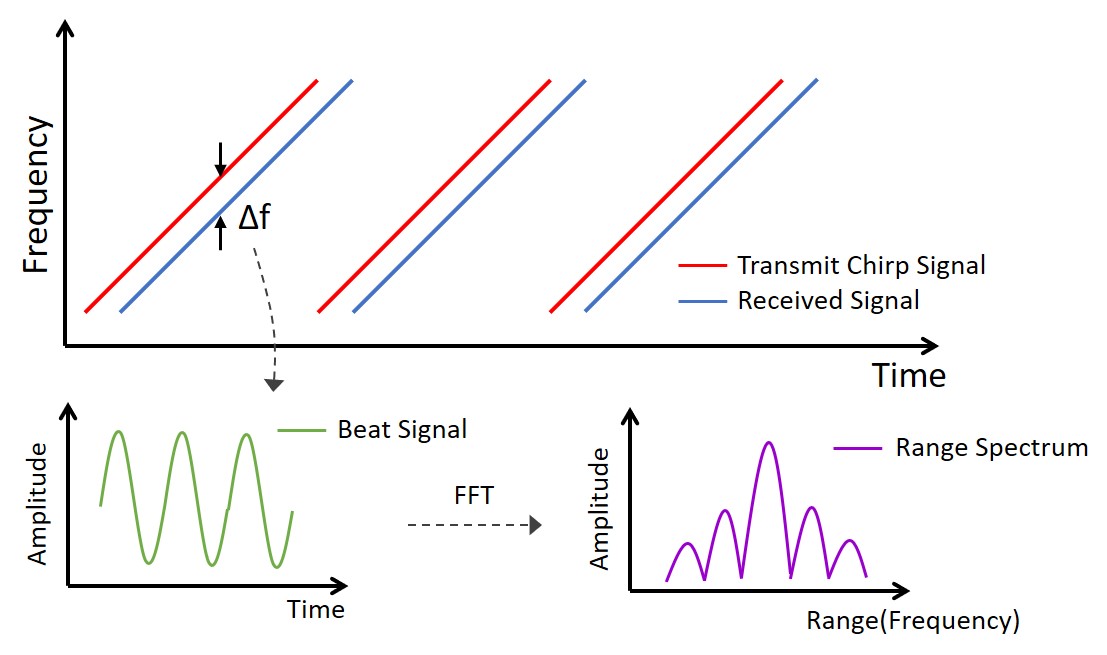
The range resolution, for example, the smallest distance that allows separate detection of two targets at different distances, depends on the modulation bandwidth of the transmitted signal and improves proportionally to the increase in bandwidth. Besides, the radar can determine the velocity of the target simultaneously with the distance. It follows then that the velocity resolution can be defined similarly to the range resolution. Because of the nature of the Fourier transform, the velocity resolution improves proportionally to the increase in the number of times of repetition of the chirp signal, i.e., the increase in observation time.
Millimeter-wave bands allow the use of wideband signal frequencies ranging from several hundred megahertz to several gigahertz, thereby enabling high-range resolution. Besides, radio wave wavelength decreases with increasing frequency, thereby correspondingly allowing antenna miniaturization. Thus, millimeter-wave radar enables equipment miniaturization and high-range resolution.
2.2 Azimuth angle estimation
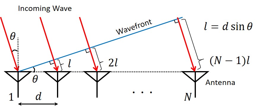
When a radar antenna is an array antenna consisting of more than one antenna and the target-to-radar distance is sufficiently larger than the dimensions of the array antenna, an incident wave can be regarded as a plane wave with a flat wavefront. In this case, the incoming signal reflected from the target to the radar is incident to each receiving antenna element with the path length difference based on the azimuth angle of the target as shown in Fig. 2. Therefore, the signals received by two receiving antenna elements show a difference in delay due to the path length difference. In other words, a phase difference occurs between the signals. Based on this phase difference, the azimuth angle of the target can be calculated. Here, the angular resolution is defined as the smallest angle that allows separate detection of two targets at the same distance.
3. Resolution required for the radar
Table 1 shows typical vehicle traveling situations and the types of resolution required for separate detection of vehicles by radar.
3.1 Tandem traveling
When more than one vehicle travels along the same lane with regular intervals in between, the vehicles seem to move at the same speed and angle from the point of view of the radar. To be detected individually in this case, the vehicles must be separated based on the distance information. The range resolution depends on the frequency bandwidth and hence can be improved by applying a wider frequency bandwidth.
3.2 Overtaking
In a situation where a fast-traveling vehicle catches up and passes a slow-traveling vehicle, separation resolution is needed most when the two vehicles are traveling side by side along their respective lanes. In this case, the two vehicles seem at the same distance from the point of view of the radar. To be detected individually, the vehicles must be separated based on either the velocity information or the angle information. The velocity resolution improves with increasing observation time. Hence, this situation can be handled by securing sufficient observation time.
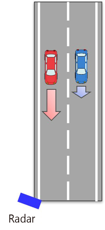
| Situation | Tandem traveling | Overtaking | Parallel traveling |
|---|---|---|---|
| Conceptual image | 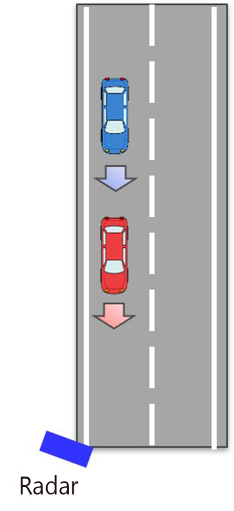 |
 |
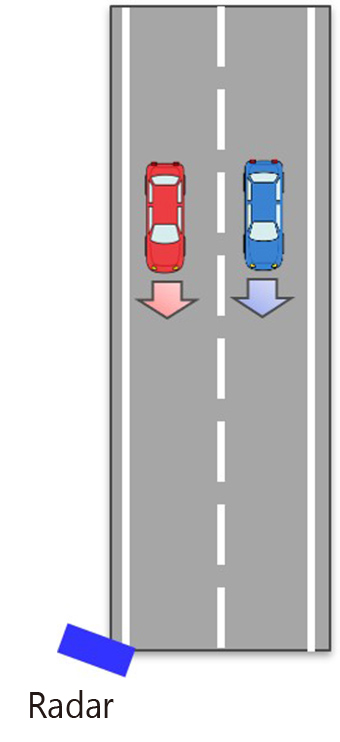 |
| Required resolution | Distance | Velocity/angle | Angle |
3.3 Parallel traveling
In a situation where two or more vehicles travel side by side along adjacent lanes, the vehicles seem at the same distance and the same speed from the point of view of the radar. Therefore, they must be separated based on the angle information. Constrained by the number of antennas, radar has more difficulty in angular resolution enhancement than optical system sensors. Thus, parallel traveling is one of the detection situations challenging for radar.
The angular resolution essentially depends on the antenna beamwidth. This dependence gives rise to the need to narrow the beamwidth of each antenna or increase the number of antennas. Attempts to deal with these needs through antenna characteristics alone would result in additional problems. In the former case, a smaller detection area would result; in the latter case, larger radar equipment, or an increased manufacturing cost would result. Therefore, the required solution is to provide an angular resolution that allows separate detection of individual vehicles with a limited number of antennas.
What becomes of importance, in this case, is the characteristics of the DOA estimation method for estimating the azimuth angle of the target. The Beamformer method is a conventionally used method based on the Fourier transform. Its limitations is what our proposed method intends to overcome. Table 2 compares the characteristics of the Beamformer method with those of alternative DOA estimation methods expected to provide higher angular resolution than the Beamformer method.
Both the LP and MUSIC methods may provide a high angular resolution. What characterizes the MUSIC method is, however, that it performs eigenvalue decomposition of the correlation matrix of a received signal. For each of the resulting eigenvalues (eigenvectors), an angular spectrum is obtained as an DOA estimation result. In practice, however, factors, such as the influence of noise, may cause spurious outputs, which are erroneous DOA estimation results. The MUSIC method applies parallelized composition to such spurious outputs. This method has as its advantage the ability to reduce spurious outputs by means of MUSIC spectra. Hence, we considered that separate detection of parallel traveling vehicles, which has been unachievable by millimeter-wave radar used as an infrastructure sensor, would become possible by adopting the MUSIC method, a method most expected to improve the angular resolution compared to the conventional Beamformer method and to reduce spurious output as the DOA estimation method.
| Method | Outline | Resolution |
|---|---|---|
| Beamformer | Scans the main lobe omnidirectionally to determine an azimuth angle that maximizes the array antenna output power. | Dependent on the beamwidth formed by the array antenna |
| Capon5) | Minimizes the contribution of azimuth angles outside the main lobe to the array antenna output power. | Dependent on the beamwidth formed by the array antenna |
| LP6) | Performs null-scanning to minimize the array antenna output power. | Higher resolution than that of Beamformer or Capon |
| MUSIC7) | Uses the orthogonality between signal and noise subspaces to perform scanning with MUSIC spectra. | Comparable to LP Reducing spurious output |
4. Experiment
For an actual situation with parallel traveling vehicles, an experiment was performed to verify the effect of the MUSIC method on the improvement of separate detection.
4.1 Millimeter-wave radar for verification
Table 3 shows the specifications for the millimeter-wave radar system used in the experiment. This radar system is a Multiple Input Multiple Output (MIMO) radar system with two transmitting and four receiving antennas. The number of receiving antennas in the virtual array totals eight. The range resolution and the velocity resolution determined based on the frequency bandwidth and the observation time are 0.4 m and 1.0 km/h, respectively, and provide the performance necessary to achieve separate detection of vehicles in tandem-traveling and overtaking situations.
| Method | FMCW |
|---|---|
| Number of antennas | 2 transmitting and 4 receiving antennas |
| Center frequency | 76.5 GHz |
| Frequency bandwidth | 340 MHz |
| Observation time | 6.5 msec |
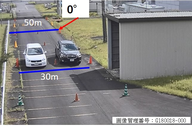
4.2 Experimental environment
Fig. 3 shows the experimental environment as viewed from the installed radar. The radar was installed at 6.75 m above the ground level, taking into account the environment expected for it to be installed in as an infrastructure sensor. The road was 5.8 meters wide, allowing for an assumption of a two-lane road. To simulate a situation of monitoring vehicles from the road shoulder, the radar was installed, as shown in the figure, at a point 50 meters deep and 0 degrees relative thereto. The two vehicles traveled side by side at approximately 30 km/h towards the radar.
4.3 Experimental results
The angle estimation results for the two vehicles passing the point 30 meters away from the radar were examined to determine whether the radar allowed separate detection of the two parallel traveling vehicles. Fig. 4 shows the range and velocity estimation results based on the signal received when the vehicles passed the point 30 meters away. The velocity of the vehicles was detected as a negative velocity during their approach to the radar. As the figure shows, a peak occurred at a distance of 30 meters and a velocity of −9 m/s (−32 km/h). This peak represents the detection of the two parallel traveling vehicles. In fact, however, what the figure shows are two peaks occurring at the same point to overlap each other because the vehicles traveled the same distance at the same speed towards the radar. This overlap of the two peaks means the failure of separate detection of the parallel traveling vehicles based on the distance information and velocity information.
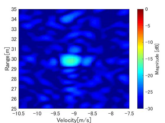
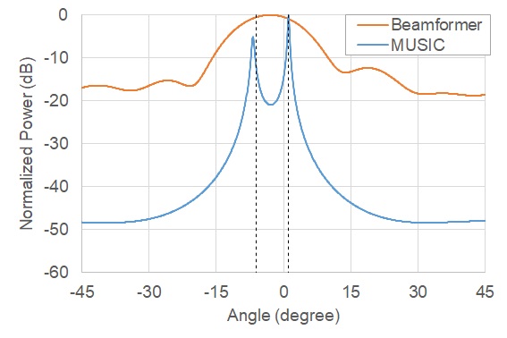
Fig. 5 shows the azimuth angle estimation results obtained by the Beamformer and MUSIC methods for the two vehicles passing the point 30 meters away. Table 4 shows the true azimuth angle (true value) of the parallel traveling vehicles to the radar and the peak values read from the estimation results in Fig. 5. What is expected here is the occurrence of two peaks corresponding to the parallel traveling vehicles. The results, however, show that both methods failed in separate detection. The MUSIC method supposedly provides a higher angular resolution than the Beamformer method. This method, however, relies on eigenvalue decomposition of the correlation matrices of received signals and hence has the drawback of reduced performance when a strong correlation holds between signals reflected from more than one target. It seems that this drawback strongly manifested itself for the signals reflected from two objects close to each other, in other words, the two parallel traveling vehicles in this experiment.
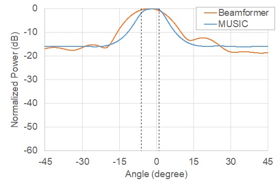
| True value | Beamformer | MUSIC | |
|---|---|---|---|
| Estimated angle | −6.2, +1.0 deg | −2.9 deg | −0.3 deg |
To deal with the above problem, spatial smoothing preprocessing8) was applied to suppress the correlation between the signals. When used for correlation matrix computation in azimuth angle estimation, spatial smoothing preprocessing divides the whole array antenna arrangement into several partial array arrangements called subarrays and finds the mean value of the correlation matrices of the subarrays. Even correlated signals undergo phase shift when their receiving positions are shifted, whereby the correlation can be suppressed by averaging the receiving positions shifted as a result of the division of the array into subarrays.
Fig. 6 shows the azimuth angle estimation results obtained by the application of spatial smoothing preprocessing to the calculation by the MUSIC method. The estimation results for the MUSIC method clearly show the occurrence of two peaks. As shown in Table 5, the estimated angles represented by the two peaks agree well with the true value, respectively.
| True value | Beamformer | MUSIC | |
|---|---|---|---|
| Estimated angle | −6.2, +1.0 deg | −2.9 deg | −6.9, +1.1 deg |
4.4 Discussions
For the results of detection by the MUSIC method, the difference between signal power and noise power (SNR) in the incoming wave obtained from the correlation matrix during the computing process was determined by calculation. For the detection of the targets, a minimum SNR of approximately 6 dB should be guaranteed. The SNRs for the two peak angles shown in Table 5 were found by calculation to be 9.1 dB (−6.2 deg.) and 9.9 dB (+1.0 deg.), respectively. Spurious outputs would have an SNR of approximately 0 dB. Accordingly, the two peaks obtained this time are found attributable not to spurious signals but the vehicles. The above observations show that the MUSIC method with spatial smoothing preprocessing enables separate detection of parallel traveling vehicles, which has been unachievable by the conventionally used Beamformer method.
5. Conclusions
Assuming the use of millimeter-wave radar as an infrastructure sensor, the MUSIC method, a high angular resolution method, was applied to a parallel traveling vehicle situation, which was particularly challenging for radar sensor systems to examine whether it allowed separate detection of the vehicles.
A real vehicle-based verification simulating a monitoring situation from a road shoulder was performed to demonstrate that the MUSIC method enabled the separation of parallel traveling vehicles, which had been unachievable by the conventionally used Beamformer method. Moreover, this paper revealed that spatial smoothing preprocessing can effectively suppress the correlation between signals reflected from parallel traveling vehicles. From the above observations, this paper demonstrated that the use of millimeter-wave radar as an infrastructure sensor allowed the separation of parallel traveling vehicles, which had been unachievable by conventional methods.
In the future, we will conduct more evaluation experiments under various environments. Also, we will explore the application of additional high angular resolution methods, such as virtual array extension methods based on the Khatri-Rao Product9), which is expected to improve angular resolution without the need to change the antenna configuration. Furthermore, we also intend to optimize antenna performance to suit detection areas.
Acknowledgment
This paper constitutes part of the collaborative research achievements with National University Corporation Niigata University. We would like to express our cordial appreciation to Prof. YAMADA Hiroyoshi and Mr. HORIUCHI Takahiro at Niigata University.
References
- 1)
- Central Traffic Safety Counter-measurement Council, “The 10th Traffic Safety Basic Plan” (in Japanese), https://www8.cao.go.jp/koutu/kihon/keikaku10/index.html, (accessed Aug. 5, 2019).
- 2)
- Traffic Planning Division, Traffic Bureau. “On the Traffic Death Toll for FY 2018” (in Japanese), http://www.npa.go.jp/news/release/2019/20190104jiko.html, (accessed Aug. 5, 2019).
- 3)
- Cabinet Office, “On the Implementation of Demonstration Experiment at Tokyo Waterfront Area ~ SIP ʻAutomated Driving (Extension of System and Service) ~ʼ ” (in Japanese), https://www8.cao.go.jp/cstp/stmain/20181113_adusrinkai.html, (accessed Aug. 5, 2019).
- 4)
- U. Dai, H. Takahiro, S. Yuta, S. Keisuke, and Y. Hiroyoshi, “A Study on Vehicle Separation using Incoming Direction Estimation for Millimeter-Wave Radar” (in Japanese), in Proc. IEICE General Conference 2019, p. 165, B-1-165, 2019.
- 5)
- J. Capon, “High-Resolution Frequency-Wavenumber Spectrum Analysis”, Proc. IEEE, Vol. 57, No. 8, p. 1408-1418, 1969.
- 6)
- D.W. Tufts and R. Kumaresan, “Estimation of frequencies of multiple sinusoids: Making linear prediction perform like maximum likelihood”, Proc. IEEE. Vol. 70, No. 9, pp. 975-989, 1982.
- 7)
- R. O. Schmidt, “Multiple Emitter Location and Signal Parameter Estimation”, IEEE Trans., Vol. 34, No. 3, pp. 276-280, 1986.
- 8)
- T. J. Shan, M. Wax, T. Kailath, “On Spatial Smoothing for Estimation of Coherent Signals”, IEEE Trans., Vol. 33, No. 4, pp. 806-811, 1985.
- 9)
- W.-K. Ma, T.-H. Hsieh, and C.-Y. Chi, “Estimation of Quasi-Stationary Signals With Less Sensors Than Sources and Unknown Spatial Noise Covariance: A Khatri–Rao Subspace Approach”, IEEE Trans., Vol. 58, No. 4, pp. 2168-2180, 2010.
The names of products in the text may be trademarks of each company.