


Development of a new system using extraordinarily small self-controlled run robot
- Extraordinarily small self-controlled run robot
- New production system
- Functional investment analysis
- Low-cost pickup and placing robot
- Nonsynchronous transfer
In recent years, in order to grow further while maintaining its competitiveness in the environment surrounding the electronic parts business(Electronic &Mechanical Components, hereinafter referred to EMC), it is necessary to realize manufacturing that meets various customer’s demands.
Conventional EMC products have been produced almost by automatic machines. However there are two problems in production in automatic machines. First problem is that the investment is not suitable for the request which number are less than 100,000 pieces per month, and second problem is that the development period is long. In order to solve these two problems, we devised a new production system. This system reduced the investment of the process not to produce value and enabled the automation of an important process qualitatively.
In addition, a customer was able to realize manufacturing to provide value by assuming facilities production period 1/2.
In this paper, we report on the development of new production system using flexible conveyance technology by extraordinarily small self-controlled run robots, its results and future development. About a challenge to automation in small-lot production territory.
1. Introduction
Amid changing and diversifying customer needs in recent years, it is necessary to offer products customized for each customer and to shorten the development period. In addition, in the production field, it is also necessary to solve issues such as rising labor costs and securing production personnel. Furthermore, rapidly growing competitors in emerging countries are becoming a threat in terms of not only cost, but also quality. To facilitate further growth while remaining competitive in the environment surrounding the electronic parts business (Electronic & Mechanical Components, hereinafter referred to “EMC”) like this, it is necessary to realize manufacturing that meets various customer needs.
In this paper, we report on our efforts on a new production system for low-volume production developed to solve these issues and to satisfy both customer and managerial satisfaction.
2. The need for a new production system
Conventional EMC products have been mainly produced by automated machines. The automated machine-based production system is effective for high-volume production of more than one million units per month, because of its short production tact time. On the other hand, investment in automated machines for lowvolume production raises the following issue. Automated machine need to have a jig section composed of high-precision parts so as not to affect assembly and inspection accuracy. In addition, they also need a high-precision and high-rigidity structure to transfer the products to subsequent processes at high speed and to stop them with a high degree of accuracy. Therefore, their bases need to be equipped with a heavy and highly rigid mounting frame.
This base is called a “base machine,” and using it in the production of customized products with low production volume increases the depreciation expense significantly, leading to strong cost pressure. In addition, for production using automated machines, investment needs to be made based on a sales projection in expectation of future increase in demand. Therefore, when the production volume is low, significant investment has to be made at the time of launch even in performances which are not required immediately (such as high transfer speed and unused processes).
A base machine in an automated machine is like a bullet train which stops at every station on a local line. In spite of enough preparation of heavy-duty railway tracks and platforms suitable for bullet trains, and s escalators and elevators for transporting passengers, there are only few passengers. Although these facilities are built in expectation of the future development of the area around the station, everyone can see that this is not an investment which needs to be made now. However, on actual production lines, such investments are made in many cases. The effective utilization of automated machines is achievable by launching production through investment, which is commensurate with the production volume, in the production stage to increase production capacity in proportion to the expansion of business little by little in the growth stage, but not by preparing automated machines with production capacity in expectation of the mature stage of the product cycle in the launch stage. And in the decline stage, the parts of the production line, in which investment was made in the growth stage, are converted to other models.
2.1 Appropriate cost and Quick launch commensurate with production volume
Low volume production is one of various customer needs. To satisfy such need, it is necessary to drive down manufacturing costs even in low volume production. It is hard to invest in automated machines in the field of low volume production, and the reduction in investment based on automated machines is approaching its limit. On the other hand, in manual assembly production, the situation is such that labor costs are soaring and it is becoming very difficult to secure personnel. In the current production system, it is very difficult to realize the automation of manual assembly operations and the reduction of investment at the same time.
For example, the first-year production volume of more than 80 percent of our EMC products is smaller than 100,000 units per month, and the shortening of their development period is also required. The automated machine-based production system applied to the production volume of more than one million units per month results in high manufacturing costs, which cannot meet customer requirements. If we cannot meet customer requirements, customers will decide to do business with other company, and we will lose business opportunities.
Because the production volume is low in the launch stage of the product life cycle, quick launch, which is commensurate with the actual production volume requested by a customer is required. In short, the quick establishment of a production line by making capital investment, which is commensurate with production volume, leads to achieving both customer and managerial satisfaction.
2.2 Phased investments following an increase in production volume
As described above, in the launch stage, a launch by making capital investment, which is commensurate with the production volume required by a customer, is needed. On the other hand, after the release of the product, it is necessary to flexibly cope with an increase in production volume, while continuing the supply of products satisfying customer requirements. This is because the required production volume changes from moment to moment, due to increases in sales of customers’ products on which our EMC products are mounted, as well as the expansion of sales to other customers.
In conventional automated machine-based production, automated machines with production capacity in expectation of the mature stage were prepared in the launch stage, because conventional automated machine-based production system cannot respond to increases in production capacity following an increase in production volume in the growth stage.
However, if investment into automated machines in the launch stage in expectation of the mature stage does not reach the predicted production volume, the production line will need to be stopped. In short, automated machines which cannot be used for production and generate no profit will continue to occupy space in the factory. On the other hand, in the case of a significant increase in orders owing to the adoption of our product by other customers, a second production line will be established, but a loss similar to the aforementioned one will result. To solve the issues with this conventional automated machine-based production system, it is necessary to create a new system which enables investment commensurate with the required production volume as explained in Section 2.1 and to make phased investments to secure production capacity in proportion to an increase in the required production volume.
2.3 Conversion into other models associated with a decrease in production volume
As described in Sections 2.1 and 2.2, Appropriate cost and quick launch in the launch stage and phased investment in proportion to increases in the required production volume enable customer requirements to be met. However, following the mature stage, non-operative automated machines become undesired legacy in the decline stage, because the production volume required by a customer decreases.
In such a case, phased investment works effectively, if a production system, which enables phased investment in proportion to the required production volume, is available. This is because investment in proportion to requirements can be applied not only to cases where the required production volume increases, but also to cases where it decreases. Converting part of the production line which was expanded by phased investments to another production line enables a decrease in production volume, and a further advantage is that the unit can be used for other models. This contributes significantly to increases in the asset turnover rate of ROIC, as well as the shortening of the development period of other models.
To meet the need for a new production system, we conducted a study based on a concept which was totally different from that of conventional automated machine-based production. The concept is explained below.
3. The concept of the new system (V = F/C)
For the more effective utilization of investment, after conducting research about how much investment was made into which part of a production line, we determined the concept of the new production system. As a result of a functional investment analysis, we found that the processes of transferring objects (hereinafter referred to as “transfer”), as well as of supplying parts and products (hereinafter referred to as “supply”), were invested a relatively large amount. Although they are essential processes in manufacturing, no added value is produced since they do not change product shapes. We also found that these processes were common to all production lines, regardless of the difference in product lines (Fig. 1).
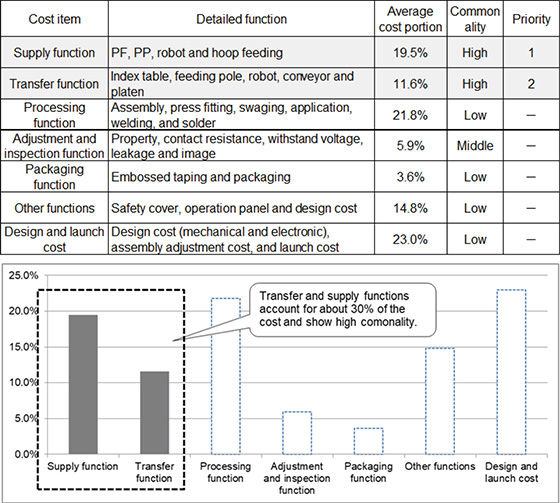
Furthermore, many transfer and supply processes have higher performance than needed for production because many commercially available units are used, such as a transfer device which can move to the next process in less than a second and a robot which can transfer objects of several kilograms in weight in less than a second.
When determining a production system which is commensurate with the production volume required by a customer, the key point is to make these transfer and supply processes flexible. Therefore, we designed a station which enables phased investments following an increase in production volume and a system which enables the expansion of the process by adding a transfer device. In addition, although conventional synchronized transfer devices can perform one operation per cycle, we adopted a nonsynchronous transfer system (a platen which enables autonomous travel of the respective devices, hereinafter referred to as a “self-propelled platen”) for the system so that the behavior and speed of the respective devices can be changed when needed and the processes unnecessary for a particular model can be skipped. This enabled process design that can level the cycle time which varies depending on the process.
In addition to realizing a production system which can be launched quickly, invested in in a phased manner, converted into other models and requiring a small amount of investment, it is also necessary to ensure that product quality is one of the major requirements. To create a production system which realizes reduced investment and ensures quality, we carried out quality function development (QFD) for the transfer and supply functions to clarify the relationship between the required functions and quality.
For processes which have less influence on quality, we created a means to determine and realize investment amounts satisfying a level of performance commensurate with such processes. In the case of processes which are more likely to have an influence on quality, they are thoroughly automated. Of course, since the idea of placing great importance on quality is given high priority, the reduced amount of investment can be used for quality improvement.
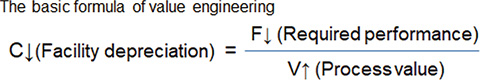
Here, we would like to introduce the concept we used for thorough investment reduction. This is a concept based on a value engineering formula, which is “V = F/C.” C represents cost and F represents the functions required for the process. Since necessary functions such as assembly and inspection cannot be changed, we replaced the functions with a level of performance commensurate with the production volume of the product and considered the functions as the value of the process. We converted this formula into “C = F/V” and conducted a study in the following two terms to reduce C (Fig. 2).
- (1)
- Increasing the value V as a process
What is the value as a process? There are various processes such as parts assembly, soldering and press-fitting processes. It goes without saying that the conventional system already satisfies this value. We reached the conclusion that increasing the value means making it possible to perform multiple operations in one process. Specifically, it is the concept of consolidating repetitive assembly and application operations into one process. This concept not only increases the value of one process, but also is effective in terms of quality control because only one application device is used to perform these operations. - (2)
- Narrowing down to the performance F which is required in the production of EMC products
What is the performance required in producing EMC products? In a process, a device equipped with various functions such as supply, transfer, processing, adjustment and inspection is installed, and in many cases, automated machines are designed using commercially available devices such as commercially available transfer devices called “base machine” and “index,” which are used in the conventional transfer devices. These devices are effective in high volume production with short production tact time, but are not required in low volume production. In addition, commercially available industrial robots are also used in supply devices. Although such robots are becoming less expensive thanks to recent advances in robot technology, they are still expensive for use in low volume production. There are many highly functional and expensive devices available on the market, but there are no devices commensurate with the performance necessary to produce electronic parts such as EMC products. On the contrary, if a device is customized to have a level of performance commensurate with the production volume of EMC products, the device cost will be high. Therefore, we decided to create our own production system which realizes both reduced investment and ensured quality.
4. Development outline
We would like to introduce two units, the transfer and supply units, which we developed to establish the new production system.
4.1 Self-propelled transfer robot
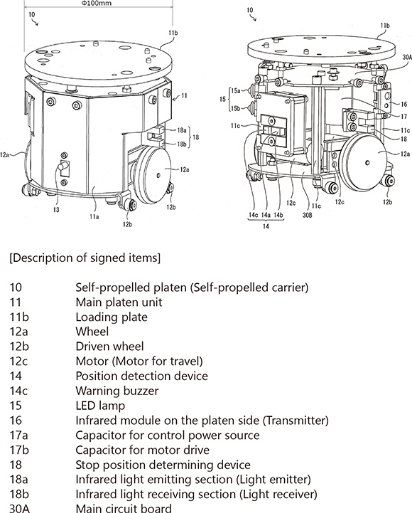
We determined the performance required for a self-propelled transfer robot which travels autonomously between processes with a workpiece loaded (hereinafter referred to as a “self-propelled platen,” Fig. 3) as follows:
- (1)
- Loading capacity: Up to 500 g
- (2)
- Travel speed: 0.5 m/sec. or higher
- (3)
- Stop position: +/− 2 mm (A locator pin is used to fix the stop position)
- (4)
- No shutdown is required when replacing the battery
- (5)
- The travel conditions for each process can be communicated when needed
The required performances described above were determined based on the quality function development, etc. (1) Loading capacity sufficient to transfer almost all kinds of EMC products. (2) Travel speed determined based on the cycle time necessary to produce 100,000 units per month. (3) Stop position calculated from the stop accuracy necessary to position the self-propelled platen in the stop state from outside. Since (1), (2) and (3) are trade-offs, we would like to introduce the relationship between the travel speed and the stop position as an effort to satisfy every performance.
Although recent advances in battery technology have been tremendous, there are no inexpensive or compact batteries which can operate continuously for more than eight hours. Doing away with the fixed concept that the driving source which operates the motor is a battery, based on the idea of realizing the performance which can transfer a workpiece to the next process at a speed of 0.5 m/sec. or higher but not the performance which operates the motor continuously for eight hours without charging the battery, we chose the method of driving the motor with a capacitor. In addition, since the capacitor is an electronic part, it requires very little charging time and it became possible to charge it during the assembly or inspection process. This also satisfied the requirement (4) that no shutdown is required when replacing the battery. Concerning the requirement (5) that the travel conditions for each process can be communicated when needed, since the distance between processes varies depending on the process, it is necessary to transmit the travel conditions for completing the travel within the required time and to receive the travel status on a process basis to realize free transfer. For this transmitting and receiving, we adopted infrared communication, which is generally used for television remote controls. Since its element is also an electronic part, it is low in cost and highly available. In using it, we make sure that interference will not occur among processes.
4.2 Low-cost pickup and placing robot
We determined the performance required for the compact, horizontal and multi-joint low-cost pickup and placing robot for supplying parts and transferring workpieces (hereinafter referred to as “LCPP,” Fig. 4) as follows:
- (1)
- Weight capacity: Up to 800 g
- (2)
- Transfer speed: Less than three seconds
(Gate motion of 30 mm in vertical direction and 300 mm in horizontal direction) - (3)
- Stop accuracy: +/− 0.015 mm or smaller
- (4)
- The operating conditions and stop position can be set on a computer
As is the case with the self-propelled platen, requirements (1)–(3) were determined as the performance required in the production of EMC products in terms of weight, speed and accuracy. We regarded the requirement (4) for the setting of operating conditions and stop position as an inexpensive but required function, considering the usability on site.
There are many high-performance robots for FA which can carry heavy objects fast. On the other hand, there are also robots for research and learning with low weight capacity and low transfer speed. Since the robots for research and learning cannot be used in the production of EMC products because their stop accuracy varies significantly, and there were no inexpensive and commercially available robots which had the advantages of both types of robots, we created a robot by ourselves.
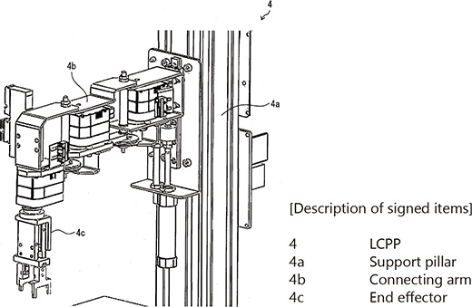
It would be good if it were able to carry light objects slowly, but the positioning accuracy is required to be as high as that of commercially available robots. In this study, using the command servo which is often used in hobby robots, we increased the stop accuracy with an external reduction gear. There is a trade-off in that increasing the gear ratio increases the stop accuracy but decreases the speed. We selected a command servo which was as high in speed and rigidity as possible to create an inexpensive horizontal multi-joint robot that ensured the required performance.
Since consumer parts are used in both the self-propelled platen and LCPP, we are using these units on an actual mass production line after conducting an evaluation of the targeted lifetime.
As we narrowed down the performance required for the self-propelled platen and LCPP to develop inexpensive devices, their spare parts were also inexpensive. We adopted O-rings for the tires which wear frequently and decided to replace them periodically once a year. If the spare parts are expensive, they tend to be used until they have a problem. However, inexpensive parts facilitate periodic replacement. As a result, the devices can maintain stable performance, which reduces problems such as short-term breakdowns of production lines.
4.3 The transfer and supply system combining the self-propelled platen with the LCPP
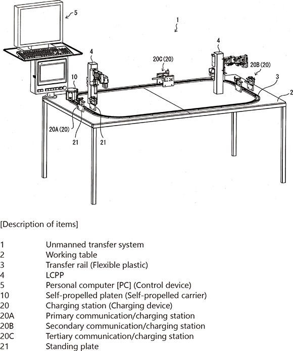
Although we developed the self-propelled platen and the LCPP as mentioned before, the self-propelled platen is not equipped with a function which allows it to go straight or go around a curve, because equipping it with such a function would increase the cost. Therefore, the self-propelled platen has only a simple function to “travel and stop,” and we used a flexible plastic rail sold by a toy manufacturer as a guide for going straight or around a curve.
The combination of inexpensive rails enabled the self-propelled platen to run on various routes, as well as to effectively utilize the area above the equipment mount. Fig. 5 shows its basic structure.
5. Development result and effect
5.1 Practical realization case example
This production system was practically realized and operated for the first time in 2016 for the assembly of a switch.
The switch assembly process is characterized by the necessity of the application of grease to the operating section. Since grease needs to be applied to many points, the part assembly and grease application operations are repeated in the process. In addition, the conventional automated machine had several grease application devices which were placed according to the order of the production process, because the operations needed to be divided to secure production capacity. Therefore, we needed the same number of transfer devices for connecting between processes as the number of processes, the percentage of cost required for the transfer function became high, and the mount for all the equipment needed to be rigid and large.
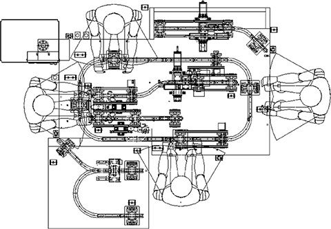
On the other hand, the practical realization we achieved this time (Fig. 6) produced the following effects:
| - Capital investment amount | 1/2 |
| - Equipment fabrication period | 1/2 (From ten months to five months) |
| - Footprint | 2/3 (From 36 m2 to 24 m2) |
We would like to explain the outline of the reduction in capital investment amount and equipment fabrication period below.
5.2 Reduction in capital investment amount
The base machines used in conventional automated machines, which were based on the method of performing the transfer operation with the platen connected, required a large drive unit and dedicated connecting parts.
On the other hand, in this system, eliminating the need for dedicated and large processed parts, as well as achieving nonsynchronous transfer, enabled the economical and most basic self-propelled platen to be utilized. Furthermore, through the effective utilization of the flexibility of the transfer route, it became possible to set up a process into which the processing devices for operations such as grease application are consolidated. This reduced the number of parts making up the equipment and resulted in a reduction in equipment size. For these reasons, compared with equipment with the same number of processes, we were able to determine that the above reduction effects could be achieved.
5.3 Reduction in equipment fabrication period
Most of the base machines used in conventional automated machines have dedicated designs and require a design period. The assembly and adjustment are the most time consuming, because complete adjustment is required owing to the connection method they were based on. Specifically, there are many cases where the adjustment of one section affects all the equipment, resulting in difficulty in completing the work.
On the other hand, this system requires a very short design period, because only the jig structure for retaining parts has a dedicated design. In addition, since the processes are not connected but individualized if accuracy is required, it became possible to adjust each process individually, as well as to minimize the number of processes which required adjustment. For these reasons, compared with equipment with the same number of processes, we were able to determine that the above reduction effects could be achieved.
5.4 A case example of utilization in quality improvement
Since this system enables a reduction in capital investment amount, as well as flexible transfer through non-synchronization, minimizing the amount of investment into non-value-added processes allows investment to be allotted to value-added processes. We utilize this investment in quality improvement through automation. We would like to introduce the following case example.
Switches are produced mainly on manual assembly-based lines and rarely on automated machine-based lines.
On a manual assembly-based line, which is straight and has workers positioned along the line, several grease application devices were required. However, even though “devices” were required, only dispensers for applying a certain amount were prepared owing to the limited investment, and work was basically performed manually. Although the application amount was controlled by the device, the condition where an operational mistake in application may occur had been regarded as problematic.
Therefore, when considering the process design of the equipment, we utilized the non-synchronous transfer function and the ability to enable flexible layout. This is “process sharing,” which makes the maximum use of automated devices.
This enabled us to consolidate our investments in the application devices which required multiple manual operations into a fully automated application device. Specifically, the parts from the processes in the former half and the parts from the processes in the latter half are transferred to automated application devices in turn from both directions, not only from one direction.
In addition, since this process sharing utilization method enables the number of devices required to be minimized, quality control operations can also be consolidated. It can be said that this utilization method for quality improvement is effective in the stabilization of quality through the promotion of automation, as well as the suppression of variations in quality.
5.5 Customer expectations and value improvement
We would like to introduce a case example where a customer’s expectations for this system resulted in the continuance of the relationship as a strong partner.
In the past, the company A, who purchased switches from us, had been requesting that we make an improvement to resolve a quality problem attributable to the conventional manual assemblybased production line. Although the production of the mainline model was increased repeatedly, we coped with the increase in production by increasing the number of manual assembly personnel. As a result, the quality problem remained unsolved. We were making efforts to make improvements but could not change the situation drastically, and the customer told us that they would consider purchasing switches from a manufacturer other than OMRON if we continued manual assembly without resolving the problem. Under such circumstances, we held an explanatory meeting for the customer. At the meeting, we made a concrete explanation for this system by comparing with the conventional production method using practically realized equipment, and the customer finally recognized its innovation. This expectation for an improvement in quality through the promotion of automation resulted in the development of a future strong partnership. We also obtained their understanding of the advantage that the fabrication period of the equipment is short, which was reflected in our business plan. From the standpoint that “on demand” – meaning how quickly needs are met – is regarded as valuable, the advantage of this system will be significant in the future.
6. Future development
6.1 Extensibility
As we were able to verify that we could obtain reliable effects from the system we studied this time, we are planning to actively promote its utilization.
Unlike dedicated processing devices, the transfer and supply system we developed this time is highly versatile. Various business units and production bases are expecting this system to be utilized on production lines of the whole range of OMRON’s products, including products other than the switch to which we applied this system this time. Specifically, from 2018, we will start the utilization of this system at overseas bases such as in China and Indonesia. In addition, we are considering introducing it at all production bases for other EMC products. Furthermore, we have started considering the utilization of this system not only in the production of EMC electronic products, but also on the assembly lines of FA products, beyond the boundaries of business units. Through the combination of manual assembly-based cell production management technology, which is good at producing FA products, with this system, we are seeking further evolution.
6.2 Mixed production
In the future, we will further pursue “Appropriate cost and quick launch commensurate with production volume” and continue development toward the utilization of this system in mixed production, which enables several types of products to be produced with only one type of equipment.
Although we already explained in Section 4 that the layout on the mount has flexibility, enabling route changes makes it possible to utilize this system in a wider range. Specifically, through the use of the ID information unique to the self-propelled platen, data on the parts to be transferred and data on the details of the work and processing performed in each process are matched corresponding to the product model to be produced to operate the self-propelled platen. Furthermore, when the parts are transferred to the next process after the work and processing are completed in the respective processes, the route change information is written programmatically and then the parts are transferred to the intended process. This mixed production system is aimed at producing further reductions in capital investment and equipment fabrication periods.
6.3 Conclusion
This system is highly flexible and has many possibilities, including those we have not yet identified. Taking the results of the efforts we made this time as an opportunity, we will continue to further upgrade this system. Through studies and discussions with all business units and companies in the OMRON group, we would like not only to achieve business results, but also to improve the motivation of all employees and leverage this successful experience to increase their pride, confidence and efforts.
References
- 1)
- Technology Roadmap WG of Manufacturing Systems Division. “Technology Roadmap by Manufacturing Systems Division (2016)”. The Japan Society of Mechanical Engineers. 2016. https://www.jsme.or.jp/uploads/sites/6/files/seisansys1.pdf
The names of products in the text may be trademarks of each company.