


High-speed Laser Scanning Technology for 2D Code with High Readability
- Laser marker
- Traceability
- 2D Code
- Galvano Scanner
- Takt Time
In preparation for responding to a recall when there is a defect in the product, it is necessary to quickly identify the recall target. In identifying the target, there is a method of assigning a 2D code that records traceability information such as the date of manufacture to the part. Laser marking is one of the ways to assign 2D codes. When performing laser marking, it is necessary to set the laser power and printing speed, but in the printing speed, there is a trade-off between takt time and printing accuracy, and it is difficult to find an appropriate set value.
A contributing factor to reduced print accuracy is the delay between the control input signal to the scanner and the actual scanner movement. In this study, in order to solve this problem, it was confirmed that printing collapse can be eliminated by automatically adding a preliminary operation to the control input. Furthermore, for example, when printing an 8 mm square 2D code, when the printing speed is set to twice that of the conventional one from 500 mm/s to 1000 mm/s, the printing time is 54% of the conventional one, and it was confirmed that significant high-speed printing can be performed.
1. Introduction
With the recent rise in public awareness of security and safety, manufacturers are increasingly held socially accountable for recalls and other post-market activities to address nonconformities encountered in final products. As a result, traceability has become more important for managing parts and manufacturing processes to enable faster target identification when nonconformities occur, besides quality improvements for preventing the outflow of nonconforming products to the market.
For instance, following the establishment of IATF 16949 in 2016 as an international standard that requires lot-by-lot traceability in the automotive industry, direct part marking (DPM) has been used to print 2D codes directly onto critical parts. In addition, with the quality requirements defined for DPM, printing accuracy can also be said to be important1).
Moreover, electronic parts are managed with assigned IDs to prevent counterfeiting and improve product yields.
DPM-based traceability methods include imprinting, inkjet printing, and laser marking. Among these options, laser marking is widely used for industrial parts because of its advantages, such as indelibility over time, zero running costs for ink and other consumables and wearable tools, and easy changeover compatible with multi-product small-lot production and fast product cycles2).
Traditionally, printing has been much needed to make it easier to manage multi-part modular units. In recent years, traceability has become a staple requirement also for individual parts constituting modules.
Although 2D-code printing with a laser marker provides many advantages, its long print cycle time poses a challenge for high-volume printing. We need a new method that achieves high-quality laser marking in a shorter cycle time.
We developed an algorithm that automatically adds a preliminary operation to the control input to the scanner depending on the printing speed setting. What follows presents this algorithm.
2. Conventional technologies and challenges
2.1 Mechanism of laser marking
A laser marker performs printing/marking by controlling and scanning laser light based on marking data edited on a graphic tool. Laser markers divide into 2D types for printing on flat surfaces and 3D types capable of printing on solid shapes as well as flat surfaces2).
Fig. 1 shows the mechanism of a typical 2D-type laser marker.
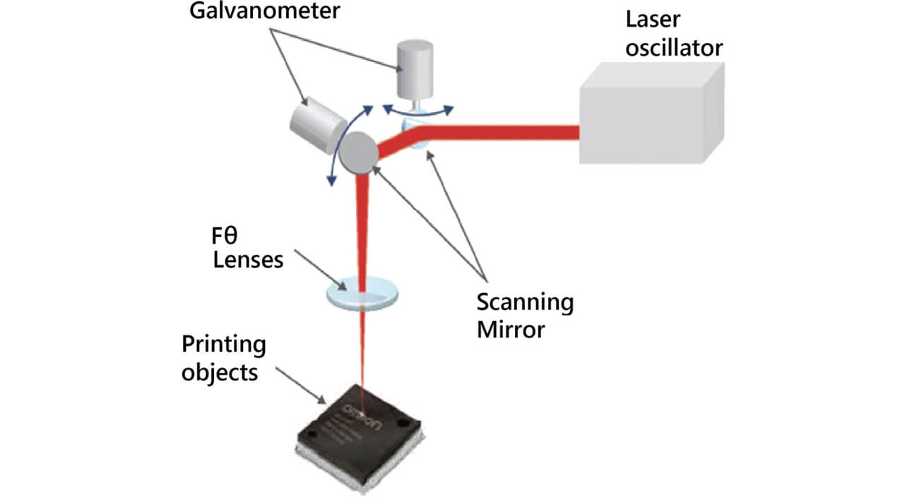
The laser oscillator emits laser light to the scan mirror. The galvanometer for adjusting the laser angle in the X- and Y-axes moves the scan mirror to aim the laser at the printing position on the print target object. The galvanometer and the scan mirror function as an integrated whole. As such, they are hereinafter referred to together as the galvanoscanner.
Printing is achieved by condensing laser light to an energy density exceeding the processing threshold and applying it to the print target object. The fθ lens is used to condense the light for 2D-type laser marking. This lens is characterized by the proportionality between the swing angle of the scanning mirror and the printing position and provides the advantage of easy scanning control.
For 2D-code printing on three-dimensional objects, such as screws, shafts, or bearings, a 3D-type laser marker is used. Fig. 2 shows the mechanism of a typical 3D-type laser marker.
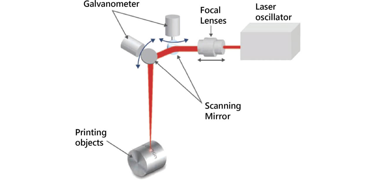
The outgoing light from the laser oscillator is adjusted by the focusing lens to the correct focus position and controlled so that focus is achieved on the print target object. The galvanometer is swung similarly to a 2D type to apply laser light to the printing position. In a 3D type, focus position adjustment is performed simultaneously with galvanometer swing angle control to suit the shape and position of the workpiece.
2.2 2D-code printing method
As explained in the previous section on the mechanisms of laser marking, a laser marker applies a micro-focused laser beam to the print target object to perform printing.
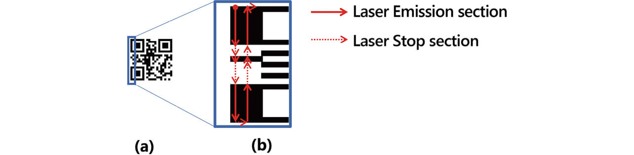
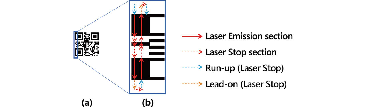
The following cases of 2D-code printing serve as examples to provide more detailed explanations. Fig. 3(a) shows the overall image of a printed 2D code. This 2D code consists of 21×21 cells, each rendered as a round shape.
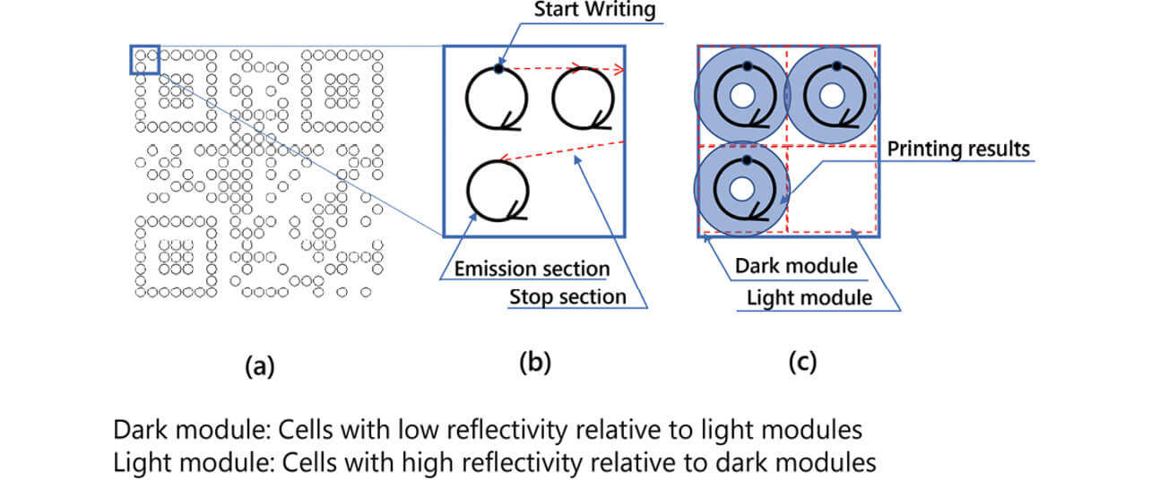
To print this code, the galvanoscanner first directs the laser beam to the print start point in Fig. 3(b). Then, a circle is drawn clockwise with the outgoing laser beam. Upon returning to the print start point, the outgoing laser beam is turned off to complete the printing of the first single cell.
Then, the laser beam is moved by the galvanoscanner to go along the red dotted line. After the print start point for the neighboring right cell is reached, the outgoing laser beam is resumed to start printing the second cell similarly to that of the first cell. These printing steps are repeated to obtain the printing results shown in Fig. 3(c).
Fig. 3 shows the laser-printed cells as dark modules. Alternatively, laser-printed cells may be converted into bright modules for a workpiece low in preprinting reflectance or by adjusting the laser irradiation energy.
For cells rendered round, depending on their size, printing can be performed so that their centers are engraved deep. Printing thus performed provides the advantage of indelibility because the centers will remain even if the surfaces are scraped by friction.
While the cells in Fig. 3 are rendered round, cells can also be rendered as straight lines as in Fig. 4.
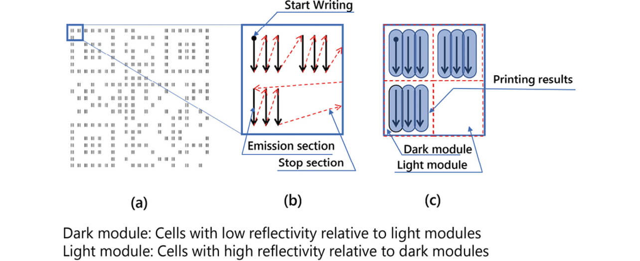
This printing allows obtaining an approximately uniform cell printing depth through printing line spacing adjustment. The printing thus obtained contains fewer visible asperities and may be evaluated as beautiful.
This ability to switch between printing methods to suit diverse needs is also one of the advantages of laser markers.
2.3 Scanning delay during character printing
This section takes character printing as an example to explain scanning delay. As explained in the section on the operation mechanisms, a laser marker performs printing by rotating the galvanometer to apply laser light to the printing point. However, inertia occurs because of the galvanometer’s rotation axis or the mirror’s mass fitted on the front end. Therefore, even if rapid mirror movement is attempted, a scanning delay will occur, resulting in a movement deviating from the instruction. Taking a case of L-shaped marking as an example, Fig. 5 illustrates the scanning delay.
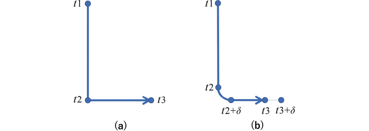
Fig. 5(a) illustrates a case of the ideal movement free of the inertia of the scanner. At time t 1, the galvanoscanner points to the print start point for the letter “L.” After the start of printing, the scanner is positioned at the corner of “L” at time t 2 and points to the print end point for “L” at time t 3. However, the actual movement is as shown in Fig. 5(b) due to the inertia of the scanner. At time t 1, the galvanoscanner points to the print start point for the letter “L.” At time t 2, the corner of the letter “L” is not reached yet because of the inertia-induced delay. However, the scanner also starts moving in the X-direction (horizontal direction) because the scanner operation start time has been reached. The time at which the movement in the Y-direction (vertical direction) reaches the horizontal stroke of “L” is time t 2 + δ inclusive of the inertia-induced delay. The printing results are an “L” printed with its corner rounded.
The scanner should then move to the print end point for “L.” However, the printing operation is terminated at time t 3, at which the print end point for an ideal operation is supposed to be reached. As a result, the L-shaped marking ends short of the ideal print end point, with the “L” printed shorter in the X-direction than intended.
Thus, scanning delay in printing with a laser marker causes a printing collapse to become apparent depending on the scanning method. To solve this problem, the OMRON-made MX-Z2000H-V1 Series laser markers are equipped with the Approach and Feed functions.
Approaching is a preliminary scanning operation performed to match the scanning speed at the laser emission start point to that during laser emission. This operation refers to scanning toward the laser emission start point during the laser-off state.
Whereas approaching is an operation performed before laser emission, feeding is a scanning operation performed after laser-off.
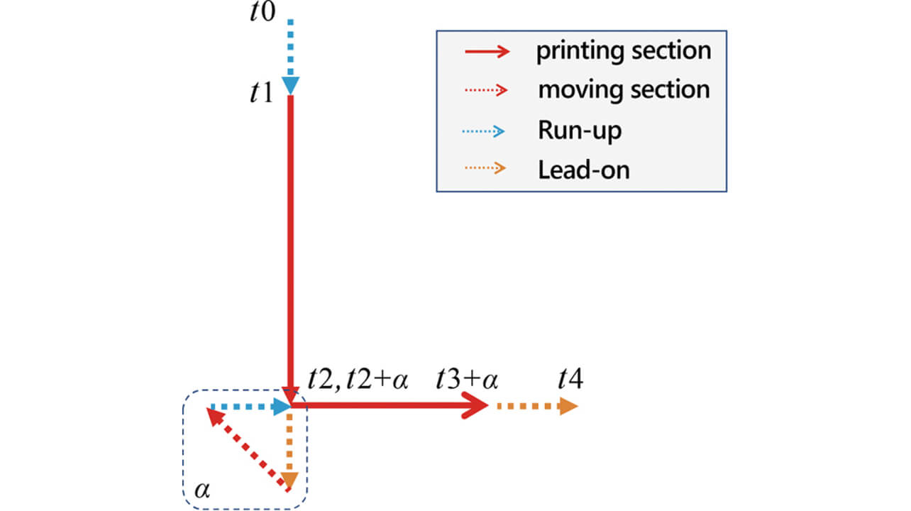
Fig. 6 shows how L-shaped marking is performed using these functions. Approaching starts at t 0, followed by laser irradiation from t 1. At time point t 1, the effect of approaching prevents the occurrence of delay. Next, with laser light emitted, scanning is performed up to the corner of the letter “L.” Then, with the laser turned off, scanning continues for the feeding distance in the same direction. With the scanning speed not reduced at the timing of laser-off, no delay occurs even at the timing of printing the corner of the letter “L.” The same printing principle applies to the horizontal stroke of “L.” While the addition of approaching/feeding results in a longer path and a slightly longer printing time, no acceleration/deceleration occurs during printing, allowing the retention of printing accuracy.
2.4 Challenges
As observed above, the accuracy of printing with a laser marker can be enhanced by improving the printing method. On the other hand, a laser marker used and integrated with a production line must meet the print cycle time requirement for coordinated operation with other processes and may be required to perform and complete printing in a short cycle time as the top priority requirement. In 2D-code printing, in particular, printing accuracy is important and hence is required to strike a balance with the cycle time.
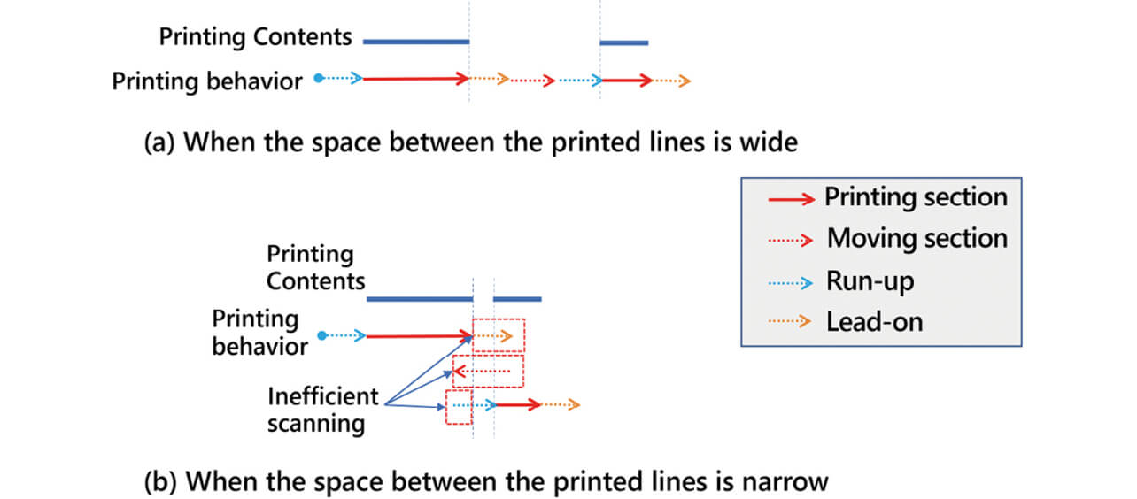
We want to improve 2D-code printing accuracy using the Approach and Feed functions that effectively eliminate scanning delay in character printing. However, this function is premised on widely spaced printing lines. In a case matching this premise, even 2D-code printing can be performed smoothly without useless actions similarly to character printing as in Fig. 7(a). The problem is that the cell size in 2D-code printing is small, often greatly narrowing the printing line spacing. When the conventional algorithm is applied under such conditions, the printing path will look like as shown in Fig. 7(b) and cause useless reciprocating motions to occur frequently thereby posing the problem of a significantly longer print cycle time.
3. Details of the present study
This study considered a printing method that minimizes the effect on the print cycle time without compromising the readability of 2D codes.
3.1 Printing path
Rapid and accurate printing requires reducing the number of accelerating/decelerating operations performed at turnarounds during print scanning. For 2D codes, such scanning can be achieved by a method that scans 2D codes on a one-side-per-stroke basis as in Fig. 8 rather than cell by cell as in Fig. 4. As a result, acceleration/deceleration occurs only at the edges of 2D codes. For rapid and accurate printing, such a printing path is desirable.
3.2 Approaching/feeding
Fig. 7(b) shows the pre-existing challenge that rapid and accurate printing performed using the Approach and Feed functions does not exert its effect where printing line spacing is extremely narrow. In the present study, we made an improvement that adds approaching/feeding to printing turnaround points to allow such a smooth operation as shown in Fig. 9 so that the scanning speed remains constant in sections with laser emission and thereby making rapid and accurate printing possible.
Moreover, we set the smallest approaching/feeding distance to be added within a range where the inertia of the galvanoscanner does not visibly affect the printing quality. We introduced automatic calculation that minimizes the print cycle time.
Because of their importance, 2D codes must be stably readable rather than merely readable. The quality index for 2D codes is defined in the International Standard ISO/IEC 15415. Besides, the quality required of 2D-code direct part marking (DPM) added on workpieces, such as that added by a laser marker, is defined in ISO/IEC TR20158. It is required that this evaluation index be referred to achieve high printing quality. Included among the 2D-code quality evaluation indices defined in this specification document is grid non-uniformity. This evaluation value rates the maximum deviation between the ideal cell position calculated by the 2D-code recognition algorithm and the actual cell position.
The setting values for approaching/feeding are automatically calculated. Thus, appropriate values can be obtained, thereby producing the effect of retaining the grid non-uniformity evaluation value (readability).
To find the minimum value of approaching/feeding distance, we measured the delay time between the actuating and position signals of the galvanoscanner. We created a calculation formula for distance conversion to reflect the result in the printing data.
3.3 Calculation formula for approaching/feeding
The delay time τ of the actual operation of the galvanoscanner relative to a signal is determined based on such factors as the scanner’s inertia, the mirror’s weight, and the driver circuit’s tuning. However, product variation can be used as a fixed parameter because almost constant characteristics can be obtained by tuning the driver circuit. The delay time τ was measured for characteristics evaluation. Besides, the algorithm was improved so that the approaching/feeding distance can be added only to 2D-code printing turnaround points to suit the user-set printing speed. The turnaround points were detected by identifying spots where the scanning angle change exceeded a certain value while the Approach and Feed functions were unused. Moreover, using Formula 1, the delay time τ was converted into the approaching/feeding distance to be added to the scanning path.

4. Experiment results
4.1 Measurement of galvanoscanner delay time
An oscilloscope was used to measure the state of the high-speed forward and backward rotation of the galvanoscanner to identify the amount of delay between the galvanoscanner control input signal and the rotation angle sensor signal. Fig. 10 shows the measurement system.
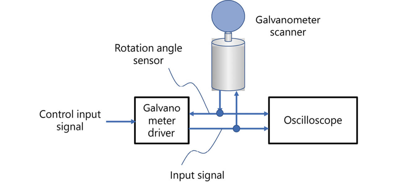
The measurement results were as shown in Fig. 11 with the delay time τ occurring between the control input signal and the rotation angle sensor signal, revealing that because of the resulting effect, the scanner started a turnaround operation without reaching the position instructed by the signal.
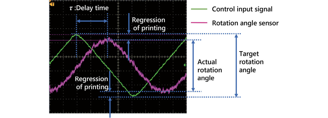
If such an operation is performed to scan in the Y-direction and print a 2D code, the 2D code will be printed and degenerated around the turnaround points.
Fig. 12 shows the state of operation with approaching/feeding added to the graph in Fig. 11 as an additional control for improvement based on Formula 1 from Section 3.3.
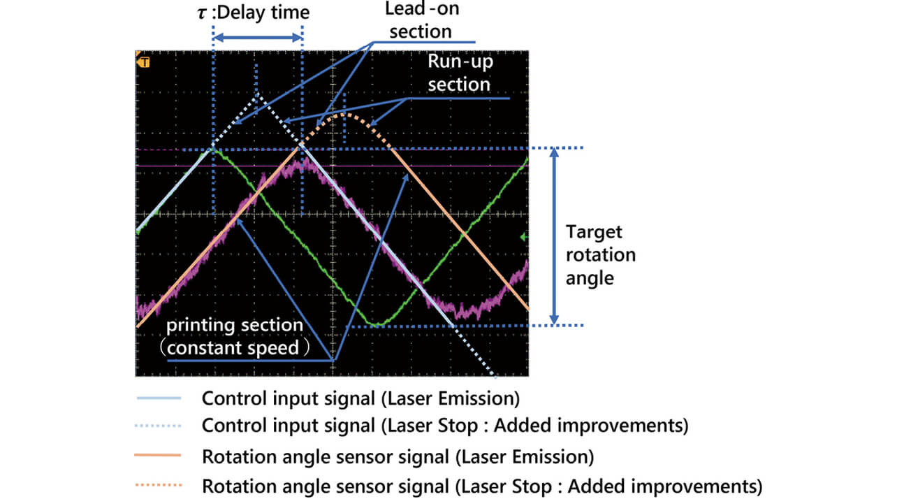
From the measurement results, the graph becomes a straight line at the timing of laser emission due to the additional control, in other words, approaching/feeding, meaning that printing can be performed at a constant speed.
Fig. 13 shows the degeneration improvement effect achieved by the addition of approaching/feeding. A look at the upper right area of the 2D code where the effect is easily visible reveals that without approaching/feeding added, the resulting printing becomes like as shown in Fig. 13(a) exhibiting some degenerations at the scanner’s turnaround points. On the other hand, Fig. 13(b) shows that the degenerations were eliminated by adding approaching/feeding.
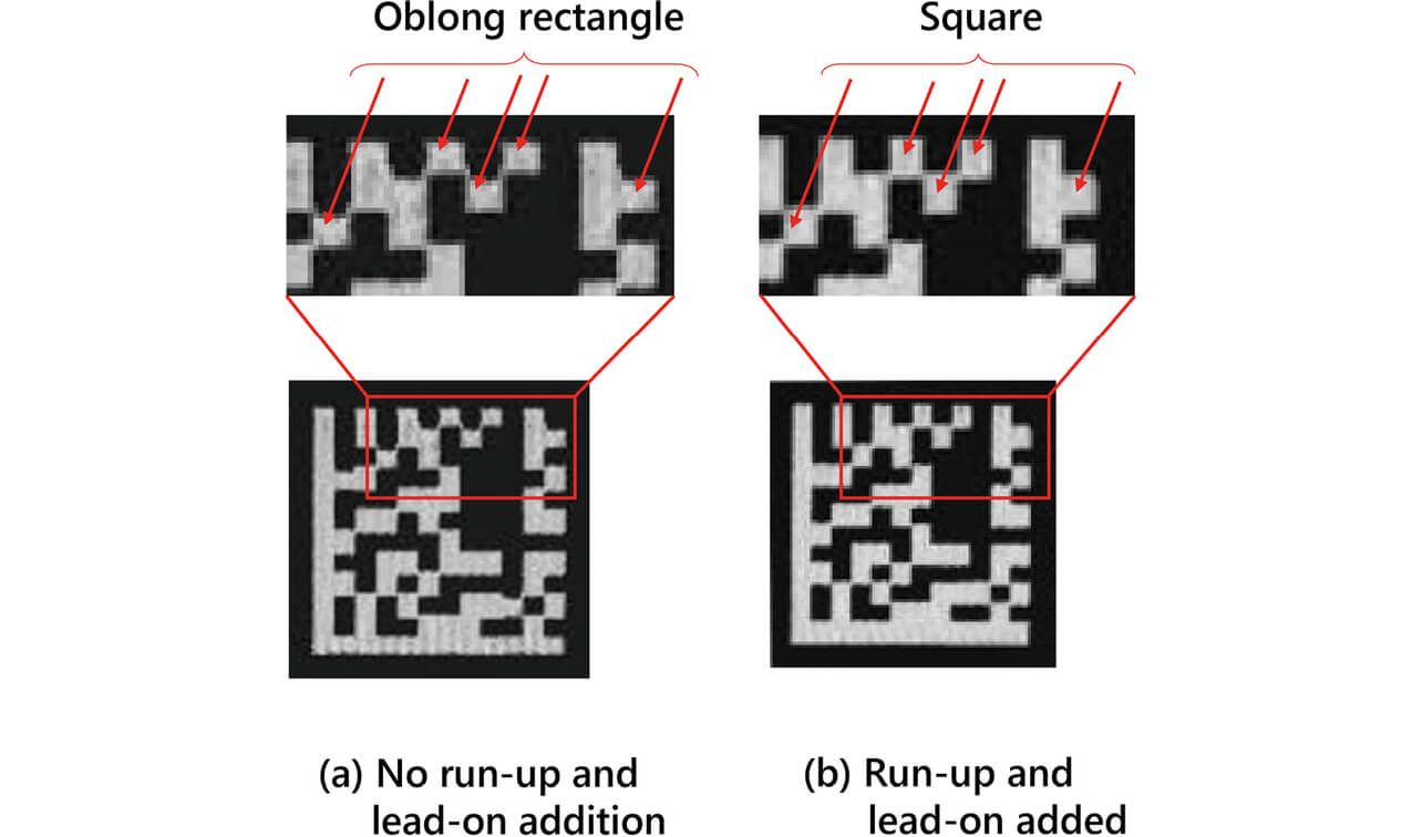
The printing results in Fig. 13 were achieved under the conditions in Table 1.
| Condition item | Value |
|---|---|
| Printed code size | 8.0 mm |
| Number of printing cells | 12×12 |
| Printing cell size | 0.5 mm |
| Printing speed | 3,000 mm/s |
4.2 Cycle time improvement effect
We estimated the printing speed improvement effect achievable by setting a twice faster printing speed. Table 2 shows the 2D code used for the estimation.
| Condition item | Estimation condition 1 | Estimation condition 2 |
|---|---|---|
| 2D code | Small | Large |
| Printed code size | 1.6 mm | 8 mm |
| Number of printing cells | 16×16 | 16×16 |
| Printing cell size | 0.1 mm | 0.5 mm |
| Number of printing scans per cell | 2 | 8 |
| Scanner delay time τ | 300 μs | |
Fig. 14 shows the cycle time estimation results. The graph with approaching/feeding added nearly overlaps with the one without and showing that the cycle time remains almost unaffected with or without approaching/feeding.
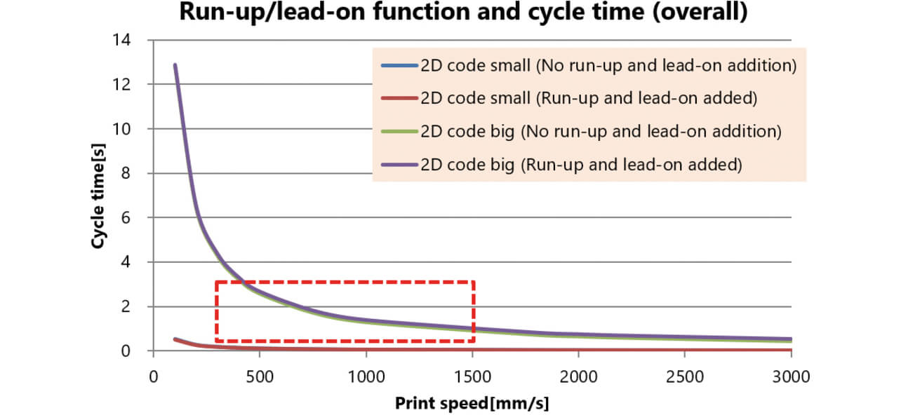
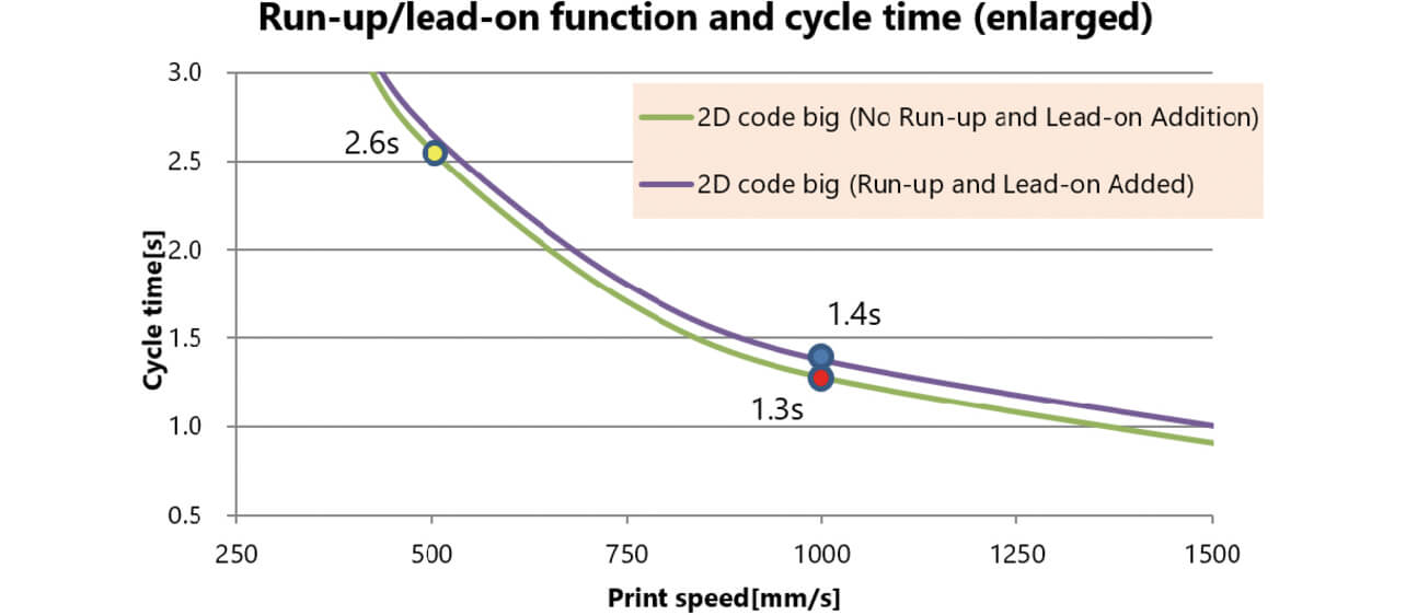
Fig. 15 is an enlarged view of the red box part of Fig. 14. Strictly speaking, a comparison of two printing runs at the same speed showed that the cycle time slightly increased from 1.3 s for with approaching/feeding to 1.4 s for without approaching/feeding. With the conventional control, the printing speed must be reduced to achieve degeneration-free printing. Otherwise, a low readability 2D code would result. To avoid this problem, we needed to take a measure, such as changing the printing speed setting from 1,000 mm/s to 500 mm/s, for example. In this case, the cycle time achievable with the conventional control would be 2.6 s. With the incorporation of the results of the present study, the cycle time became 1.4 s, which reduced the printing time to 54% of the conventional value and which can be said to be a significant time reduction.
5. Conclusions
Regarding 2D-code printing by a laser marker, we received demands for putting printing on more objects within a time limit or print cycle time reduction-related needs for performing printing within a predetermined time for coordination with other processes. However, printing speed and 2D code readability are in a trade-off relationship.
We developed an algorithm that automatically adds a minimum required approaching and feeding operations to appropriate points to suit the printing speed set for 2D codes. We confirmed that the algorithm enables rapid printing without causing print degenerations that affect readability.
The scanning technology presented here achieved print cycle time reduction. However, the viewpoint of laser power poses another rate-limiting factor, which prevents us from blindly increasing the printing speed. For low-energy print-compatible workpieces (e.g., resin parts), the technology presented here works effectively because it allows printing with the laser power doubled without changing the line thickness even at an approximately twice faster speed setting than before. However, for materials that require high laser power for printing (such as metals with high reflectance for the laser wavelength), the technology cannot provide sufficiently high laser power for high-speed scanning and has difficulty reducing the cycle time. The present study will exert its effect on various workpieces when combined with laser power enhancement efforts to suit its content. We will further evolve our laser marker to contribute to wider traceability needs.
References
- 1)
- Information Technology − Automatic Identification and Data Capture Techniques − Direct Part Mark (DPM) Quality Guideline, ISO/IEC TR 29158, 2011.
- 2)
- OMRON Corporation, Convincingly Making Sense! Laser Marker Technology Manual (in Japanese), pp. 4-5, 2019.
The names of products in the text may be trademarks of each company.