


Development of Relay Switching Mechanism that Achieves both Low Contact Resistance and High-Capacity Switching
- Low contact resistance
- High capacity switching
- Concentrated resistance
- Switching mechanism
- Impact force
In recent years, high efficiency and maintenance-free systems have been promoted in renewable energies, such as photovoltaic power generation, which are increasingly used as countermeasures against environmental problems. The increase in voltage of the system is accelerating to improve efficiency, and in order to suppress various problems in heat generation when energized with a large current, the relay used for the grid linkage section also suppresses heat generation when energized with a large current. There is a demand for a relay that can switch high capacity with high voltage and large current.
In this study, we first selected contact materials and mechanisms that achieve low contact resistance. Next, we investigated a structure suitable for peeling the contact welding generated during high-capacity switching, and the method for deriving the peeling force in that structure. In order to enable high-capacity switching, the change in momentum at the moment of peeling is set as a new design parameter, in addition to the contact force and contact follow used in the conventional design. Through this study, we established a technology for a switching mechanism that achieves both low contact resistance and high-capacity switching.
1. Introduction
With awareness growing of global warming and other environmental issues, photovoltaic power generation and related technologies drive renewable energy markets to expand. Photovoltaic power generation inverters (hereinafter “PV inverter”) convert photovoltaically generated DC voltage into AC voltage for commercial and home use, and their grid interconnection units include relays.
Relays used in grid interconnection units serve as system safety application devices for morning and evening routine system switching and emergency interruptions. In addition, these relays must accommodate large-current energization during maximum power generation. If a relay contact ON operation for large-current energization results in high contact resistance, high heat generation will occur, affecting the PV inverter. Accordingly, these relays need to have lower contact resistance than general-purpose relays for conventional applications, such as home appliances and industrial machines. To solve this heat generation problem, we set the target value for this study as an initial contact resistance of 0.2 mΩ or less, which is one of the best values achievable in the industry.
However, it takes a high-conductivity contact material to achieve low contact resistance. Contacts made of such a material would melt easily because of arc discharges during electrical switching. Hence, the possibility will increase of welded contact failure, in other words, contacts stuck together in an ON state.
Moreover, with trends in the industry toward higher voltages for the enhanced-efficiency PV inverters, high electrical insulation performance is expected of their components. Therefore, relays relating directly to the circuit-breaking function must have as wide an air insulation gap as possible in the limited available space inside. A preferable measure for this purpose would be not a single-break configuration with a single contact pair but a double-break configuration with two contact pairs in series in consideration of the wider air insulation gap available in the latter. However, a double-break configuration needs more contact points and has the problem of increased contact resistance.
Conventional technologies use contacts with additives for high-capacity interruptions and need a large contact pressure to reduce the contact resistance. On the other hand, contacts with additives are highly variable in contact resistance, posing the risk of abnormal heat generation. Another problem is that an increased contact pressure necessitates a larger relay drive coil, which increases the overall relay size. Accordingly, we adopted the following configuration to provide a relay capable of high-capacity switching with low contact resistance:
- Pure Ag contacts for achieving low energization resistance
- Two parallel current-carrying paths inside for contact resistance reduction
- A double-break configuration for safe high-voltage interruption
- Exploitation of the impulse due to the change in momentum to specify a mechanism to force open welded contacts caused by electrical switching
The argument in this paper proceeds as follows:
Section 2 presents the results of developing a theoretical equation to achieve low contact resistance, selecting a contact material, and comparing and evaluating measured values to derive a feasible configuration. Section 3 presents the forced opening mechanism selected for welded contacts and the results of considering the exploitation of the impulse calculated as a design specification from the change in momentum of the opening mechanism. Section 4 presents the results of considering the impulse design parameters for the switching mechanism based on the consideration results in Sections 2 and 3. Section 5 sums up these consideration results and presents the remaining challenges and prospects.
2. Consideration of a Material-and-Configuration Combination for Achieving Low Contact Resistance
2.1 Developing the Theoretical Equation for the Initial Contact Resistance
Relay contacts fall roughly into pure Ag contacts and Ag contacts with additives by their material. Typical Ag contacts with additives are further divided into those made of Ag + metal (Me) and Ag + metallic oxide (MeOx). Generally speaking, contact resistance is highest with pure Ag contacts, followed by Ag + Me contacts and then Ag + MeOx contacts. However, the order among these three types is reversed for welding resistance. For relays for conventional load switching, contact materials with metallic oxide (MeOx) additives resistant to arc-induced welding are selected to improve the switching performance. Meanwhile, these relays have a maximum allowable contact resistance of up to several tens of milliohms. On the contrary, relays for PV inverters must have high switching performance and a low contact resistance of 1 mΩ or less. We determined Ag + MeOx contact materials unsuitable for achieving the study’s target initial contact resistance of 0.2 mΩ or less. To consider a theoretical equation and a feasible configuration, we narrowed our choice to two types of contacts/materials: low-resistivity pure Ag contacts (contact material A with an Ag content of 99% or more); and Ag + Me contacts (contact material B with an approximate Ag content of 90%) used in conventional general-purpose relays.
A relay has three types of contact resistance: the conductor resistance of the conducting portion, the constriction resistance of the contacting portion, and the transition resistance of the contact surface. Conductor resistance can be calculated as a fixed value from the material conductivity of the conductor portion and the part shape thereof. This section considers reducing the sum of constriction resistance and transition resistance. Therefore, assuming an ideal contact resistance from a theoretical equation for constriction resistance, we considered parameter values and a configuration for bringing the measured values of constriction resistance and transition resistance as close to their theoretical values as possible. Holm’s approximation equation is known as the theoretical equation for constriction resistance of the contact contacting portion1,2):

- Rk : Constriction resistance [Ω]
- ρ : Resistivity [Ω·m]
- r : Contact radius [m]
For the contact radius, Hertzian contact theory is used1,2):

- P : Contact force [N]
- E : Young’s modulus [MPa]
- ν : Poisson’s ratio [−]
- R : Curvature radius [m]
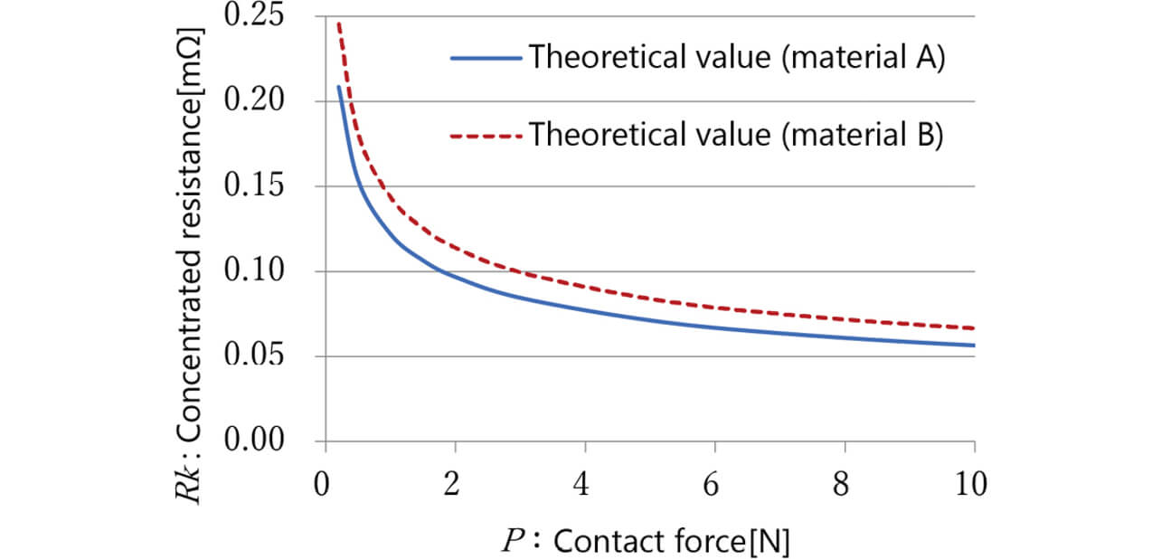
Fig. 1 shows the constriction resistance calculation results for contact materials A and B with the contact force changed based on the theoretical equation given by Equations (1) and (2). Besides, Table 1 shows the numerical values used for the calculations.
| Contact material A | Contact material B | ||
|---|---|---|---|
| Resistivity [Ω] | 1.63×10⁻⁸ | 1.92×10⁻⁸ | |
| Young’s modulus [MPa] | 90000 | ||
| Poisson’s ratio [−] | 0.33 | ||
| Curvature radius [m] |
Movable contact | 0.020 | |
| Stationary contact | Flat (∞) | ||
In the theoretical calculations, the resistivity ratio of 15% was directly reflected as differences in constriction resistance.
2.2 Measured Results for the Initial Contact Resistance
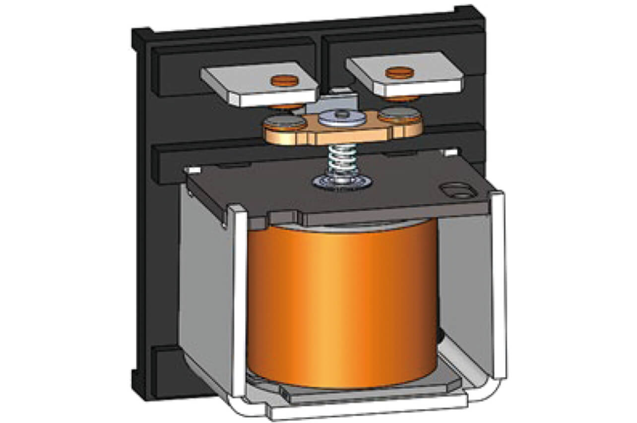
Table 2 compares the results for measuring contact materials A and B near a contact force of 2 N using the plunger-type relay configuration shown in Fig. 2. The resistance values were measured by the fall-of-potential method3). The measurement values each included a conductor resistance. Hence, the conductor resistance component values were calculated and subtracted from the measured values. Note that the configuration under measurement included two contact contacting portions. Therefore, the mean value for each pair of contacts was adopted as a measured value.
| Contact material | |||
|---|---|---|---|
| A (n=7) | B (n=4) | B/A | |
| Theoretical value [mΩ] (P: near 2 N) |
0.091~0.095 | 0.110~0.117 | 118% |
| Measured value [mΩ] (mean value) |
0.098~0.123 (0.111) |
0.156~0.170 (0.166) |
(149%) |
| Measured value/theoretical value (mean value) |
107%~132% (119%) |
142%~153% (147%) |
|
The results in Table 2 confirmed the following:
- 1) The theoretical difference between A and B is 18%. However, the measured values showed a difference of 49% on a mean value comparison basis. We estimate that this difference occurred because the measured values might include the difference in the real area of the contact contacting portion due to material hardness variations or might reflect the influences of the surface film.
- 2) Contact materials A and B had a ratio of measured to theoretical values of 119% and 147%, respectively, which were significantly affected by factors causative of a difference from the theoretical value.
From 1) and 2), we hereafter limit ourselves to contact material A to consider the difference between theoretical and measured values to achieve stable low contact resistance.
Fig. 3 below shows the results of measuring the contact resistance value with contact material A’s contact force changed using the plunger-type relay in Fig. 2. The solid line in the figure represents the theoretical calculation results for constriction resistance.
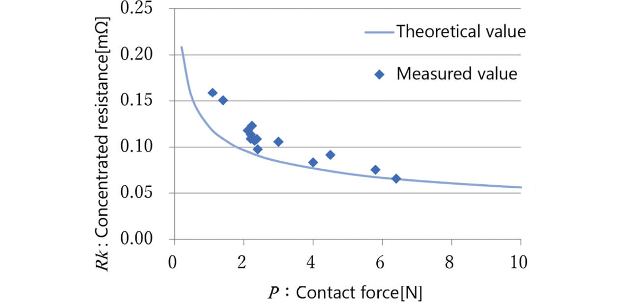
In the area where the contact force is low, the contact resistance values are scattered above the theoretical value but roughly agree with the theoretical value as the contact force increases. Fig. 4 below shows the ratio of measured to theoretical values of contact resistance relative to the contact force.
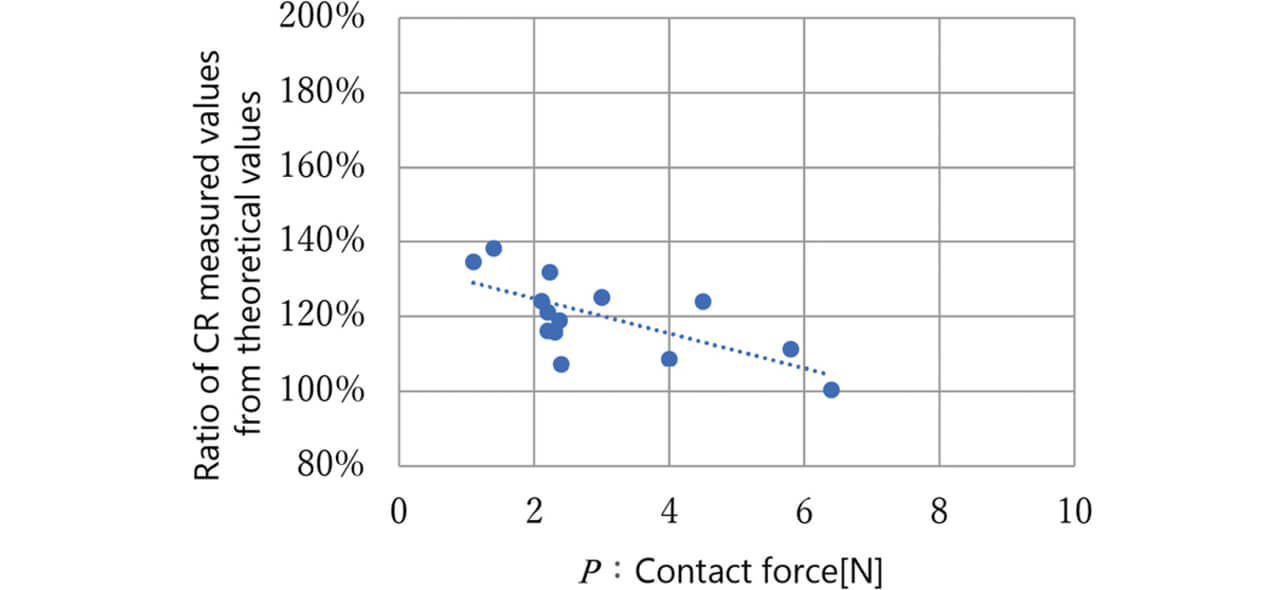
Pure Ag contacts are known to have an approximate contact force of 1 N and exhibit minor influences in contact resistance due to differences in surface roughness4). Regarding the influences of contact area and surface film, we assumed these two factors to be responsible for the difference from the theoretical equation, considering that the difference between measured and theoretical values narrows with an increasing contact force. We confirmed that an appropriate design value for contact force would reduce the above influences. The next subsection considers a configuration taking into account this difference between measured and theoretical values.
2.3 Considering a Configuration for Achieving Low Contact Resistance
As explained in Section 1, high-capacity PV inverters are of high-voltage specification. Accordingly, we adopted a double-break configuration for our relay’s switching mechanism. This configuration includes two pairs of contacts. Hence, contact resistance occurs at two locations. With an assumed conductor resistance of 0.05 mΩ, the sum of constriction resistance and transition resistance must be kept at or below 0.15 mΩ to achieve the target of 0.2 mΩ. In the case of a double-break configuration, the sum should be kept at or below 0.075 mΩ per contact pair. Then, the required contact force per contact pair is approximately 4 N relative to the theoretical constriction resistance value shown in Fig. 3. The two contact pairs need a total contact force of 8 N. A large driving force will be necessary to generate this contact force, which increases the coil block size and affecting the relay size reduction.
To solve this problem, this subsection considers a change from a single-contact configuration provided with a movable terminal serving as a current-carrying path to a twin-contact configuration with two movable terminals in parallel to reduce the contact resistance relative to the same contact force. The contact force applied at the same driving force will be split between the contacts, which increases the contact resistance per contact. However, the parallel configuration in Fig. 5 will reduce the overall contact resistance.
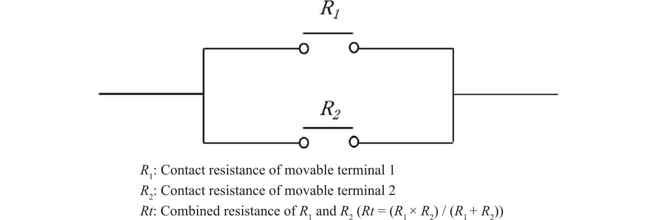
Fig. 6 shows the theoretical values for constriction resistance of a double-break/single-contact configuration and a double-break/twin-contact configuration relative to Ptotal , the sum of the contact force applied to each contact.
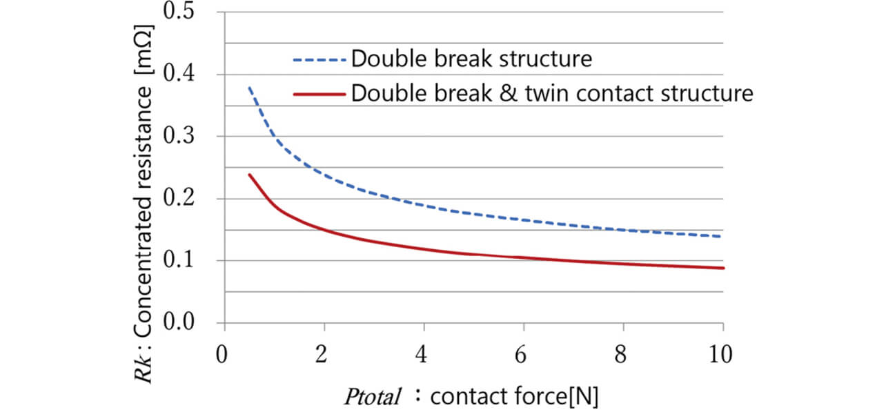
Assuming a conductor resistance of 0.05 mΩ as explained above, the allowable constriction resistance will be 0.15 mΩ. The figure shows that while the single-contact configuration needs a Ptotal of 8 N to achieve even the theoretical value, the twin-contact configuration needs only a Ptotal of 2 N to achieve it. Additionally, in the twin-contact configuration, the combined resistance difference will be small even if a contact resistance difference occurs because of the variations between the contact forces. A double-break/twin-contact configuration stabilizes contact resistance more easily than a single-contact configuration and hence is our choice here.
3. Consideration of Forcefully Opening Welded Contacts Using the Change in Momentum of the Switching Mechanism during High-Capacity Switching
3.1 High-Capacity Switching Mechanism with Pure Ag Contacts
To achieve low contact resistance, we adopted pure Ag contacts and specified a double-break/twin-contact configuration.
The mandatory function of the relay under consideration is to perform electrical switching. The problem is that a relay with pure Ag contacts is susceptible to welded contact failure due to arc discharges caused by intermittent current interruptions due to the contact bounce during electrical switching.
Welded contact failure can be avoided by either preventing welded contacts in the first place or forcing them open as need be. Welding can be prevented by eliminating contact bounces. However, a bounce-free operation is not easy to achieve with a simple mechanism for a relay that operates by mechanical action. Accordingly, we first considered a switching mechanism for a simple double-break configuration.
3.2 Considering a Forced Opening Method for Welded Contacts Exploiting the Impulse Calculated from the Change in Momentum
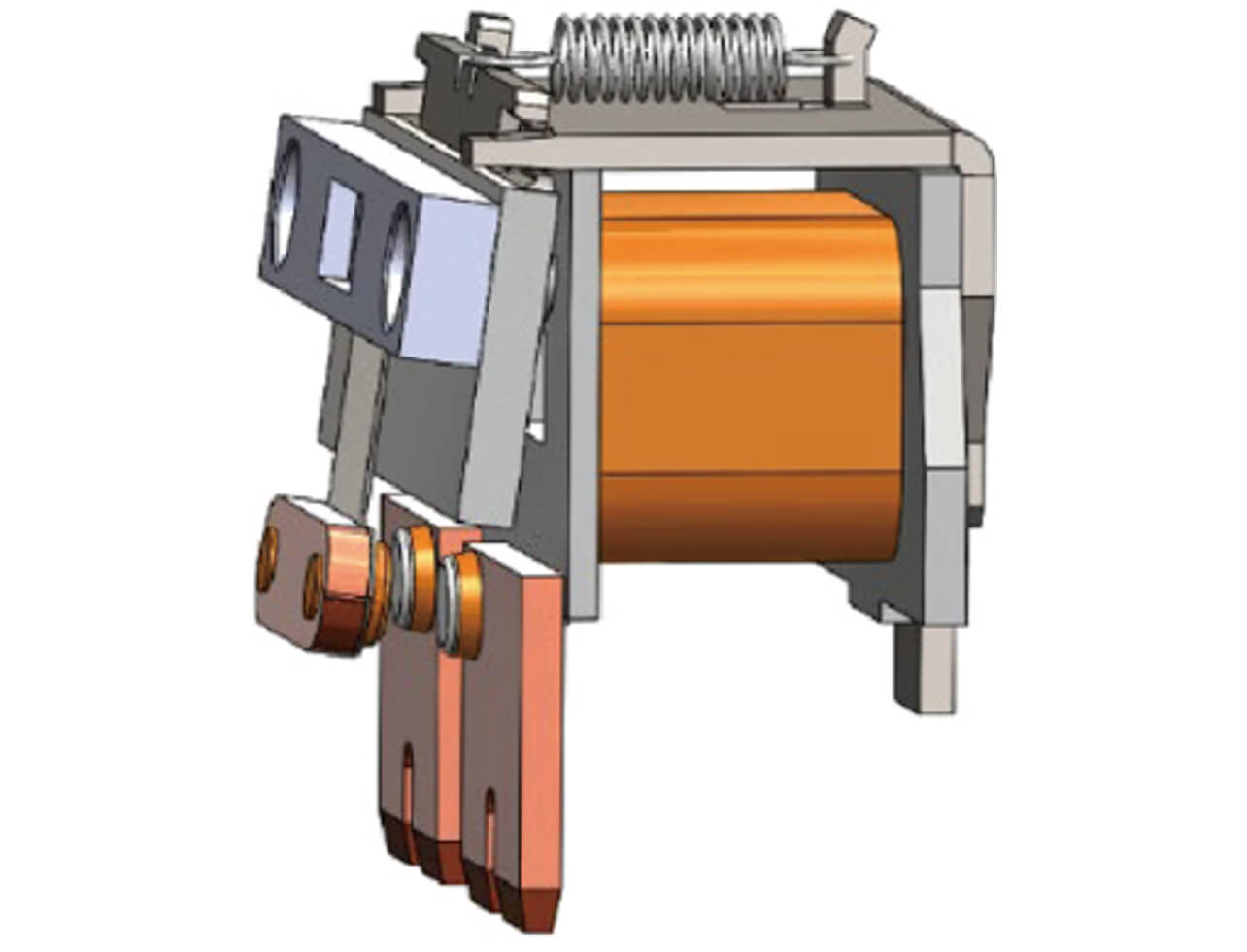
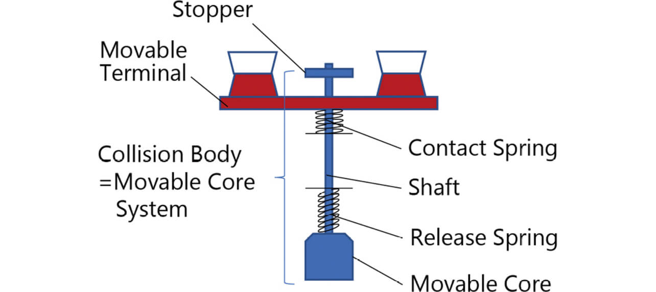
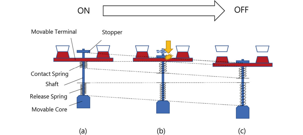
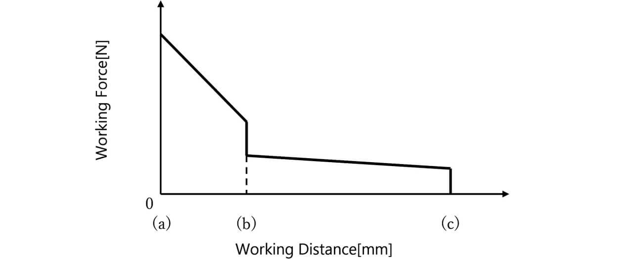
Fig. 7 shows a switching mechanism of a typical relay for PV inverter applications. This mechanism relies entirely on the spring-loaded contact opening action to open welded contacts by force. An increased spring constant or contact follow is necessary to increase the forced opening force. However, whichever solution poses the problem of an increased relay size. Meanwhile, in the plunger-type relay configuration shown in Fig. 8, the stopper connected to the movable core via a shaft collides with the movable terminal at the timing of breaking, which gives rise to a large impact force, as shown in Fig. 9. This impact force provides a promising method for forcefully opening tightly welded contacts. Fig. 9 shows State (a) with the contacts completely pushed in, State (b), the instant the contacts open during the transition from the ON to OFF state (the stopper collides with the movable terminal), and State (c) with the contacts completely reaching the OFF state. Fig. 10 shows this transition from State (a) to (c), with the horizontal axis representing the working travel of the colliding body and with the vertical axis representing the working force of the colliding body (the force produced by the contact and return springs when the movable core system is pushed in). The colliding body consists of a whole movable core system, including a movable core, a shaft, and a stopper. Since this impact force occurs because of the change in momentum of the colliding body, we considered the forced opening effect that exploits the impulse calculated from the change in momentum.
The impact force F can be calculated from the equation of motion of the colliding body as follows5):

- m : Mass of the colliding body [kg]
- a : Acceleration of the colliding body [m/s2]
- ν : Velocity immediately before the collision of the colliding body [m/s]
- ν′ : Velocity after the collision of the colliding body [m/s]
Multiply Equation (3) by Δt. Then:

Hence, the impact force F can be substituted for by the impulse I represented as the amount of change in momentum.
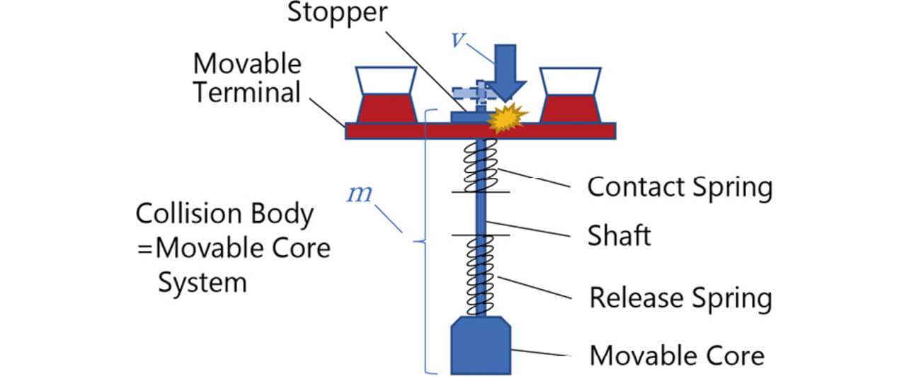
As shown in Fig. 11, the mass of the colliding body, m, is the mass of the whole movable core system, including the movable core, the shaft, and the stopper.
A high-speed camera for deriving the colliding body’s velocity was used to measure the displacement of the stopper. To ensure a more accurate determination of the instant of the stopper’s collision with the movable terminal, we used an oscilloscope and electrically obtained the timing of the opening of the contacts to perform synchronous measurement with the high-speed camera.
The stopper’s velocity immediately before contact opening was calculated from displacement to obtain the velocity, ν, immediately before the timing of contact opening. Fig. 12 shows an example of this measurement made accordingly, with the horizontal axis representing the displacement measurement time and the vertical axis representing the stopper’s displacement and velocity.
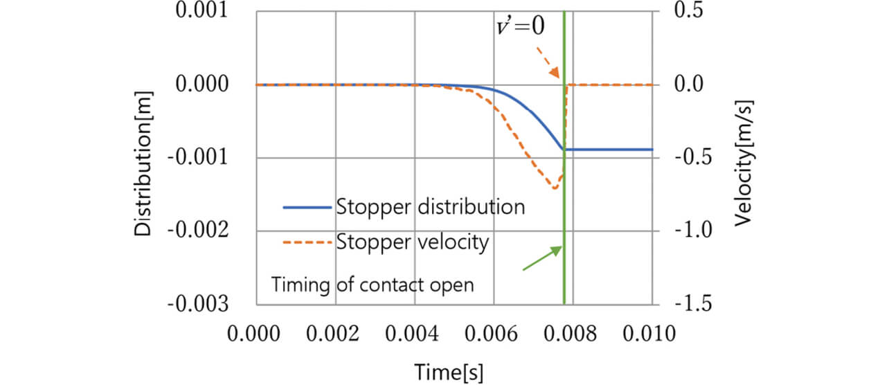
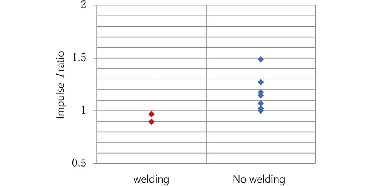
Assuming that the contacts are completely welded together, the stopper collides with the movable terminal at velocity ν, and velocity ν′ = 0, we calculated the impulse I from Equation (4) to check for I ’s relation to the occurrence of welded contact failure within the target number of ON/OFF operations for an electrical switching test. The results were polarized by the magnitude of the impulse I, as shown in Fig. 13. Here, the smallest impulse among those reaching the target number of ON/OFF operations is shown to have an impulse I ratio of 1. We identified the threshold of the impulse I to achieve the target number of ON/OFF operations.
Let us consider the impulse I from the viewpoint of the law of energy conservation. In a plunger-type relay, such as in Fig. 8, the contact and return springs accumulate elastic energy as compressed during State (a)/the relay ON state. During the transition from the relay ON to OFF state, the elastic energy is converted into the colliding body’s kinetic energy, which sends the stopper to collide with the movable terminal, causing a large change in momentum. The spring elastic energy U [N·m] consumed until the instant of the relay’s transition from the ON state to the contact OPEN state is represented here as the area of the hatched part in Fig. 14 from the relay’s working travel-vs.-working force relation in Fig. 10.
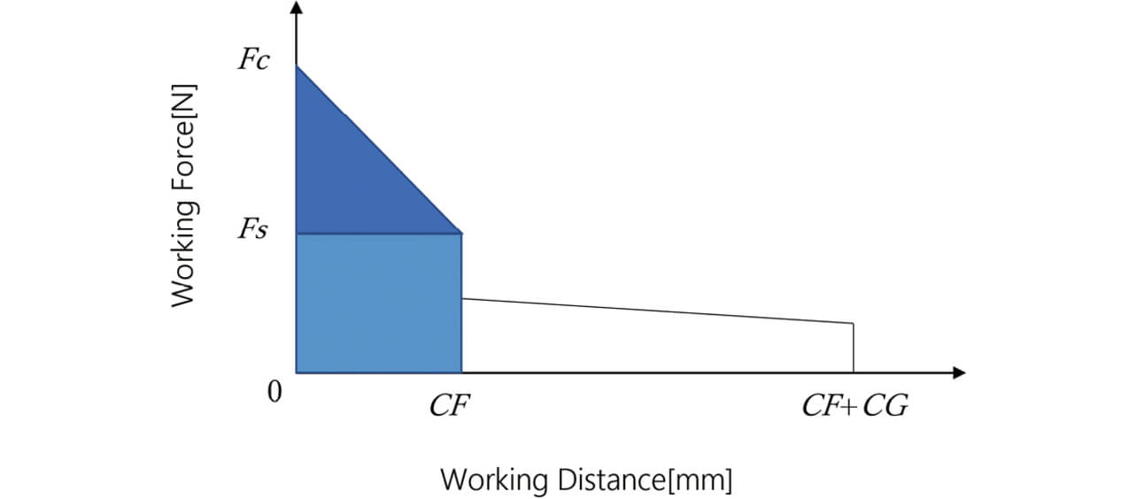

- Fc :
- Load [N] during the ON state
- Fs :
- Load [N] at the instant of contact opening
- CF :
- Movable core system’s working travel [mm] until the transition from the ON state to the contact OPEN state
- CG :
- Movable core system’s working travel [mm] until the transition from the contact OPEN state to the OFF state
Fig. 15 shows a graph with the horizontal axis representing the spring elastic energy U and the vertical axis representing the impulse I. Here, the spring elastic energy U, calculated using Equation (5) based on the values of Fc, Fs, and CF in a reference sample, and the impulse I, calculated based on the stopper velocity measured of the sample using a high-speed camera, are represented to have a ratio of 1, respectively.
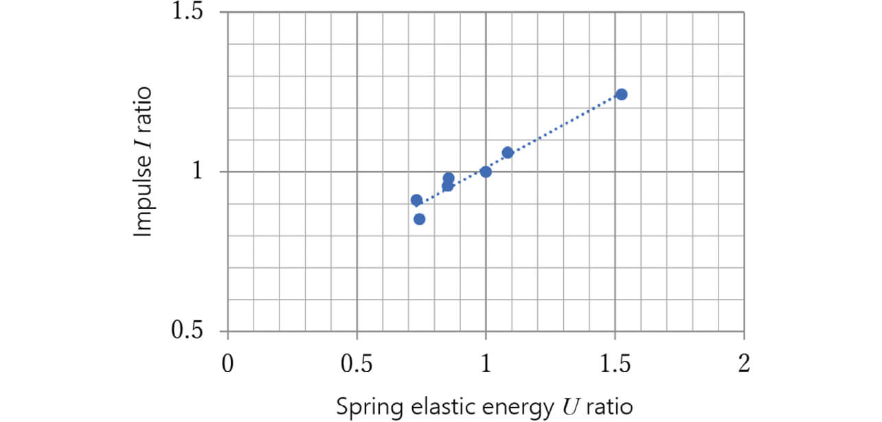
Fig. 15 reveals that the spring elastic energy U is linearly related to the impulse I. This result confirms that the welded contact-forced opening performance can be set based on spring elastic energy as a mechanism design method, similarly to the idea represented by the Charpy impact test.
4. Consideration of the Forced Opening of Welded Contacts for the Double-Break/Twin-Contact Configuration
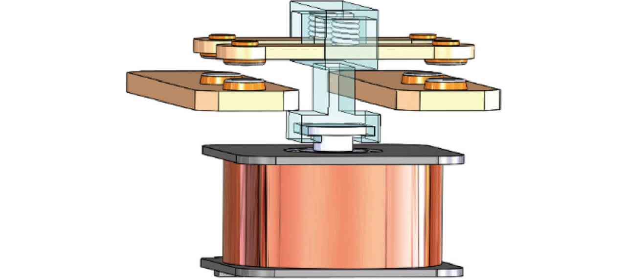
From the above consideration results, we adopted the following to allow high-capacity switching while achieving low contact resistance: a double-break/twin-contact configuration, a combination of Figs. 5 and 8, as shown in Fig. 16, for the switching unit; and a plunger-type switching mechanism.
We considered whether the idea of the consideration results for the forced opening of welded contacts by the plunger-type mechanism for the conventional double-break configuration presented in Section 3 could be applied smoothly to designing the switching performance of this double-break/twin-contact configuration with a plunger-type mechanism. The double-break/twin-contact configuration contains two independent movable terminals. Therefore, the relationship between the working force and working travel of the spring-loaded relay will be as shown in Fig. 17.
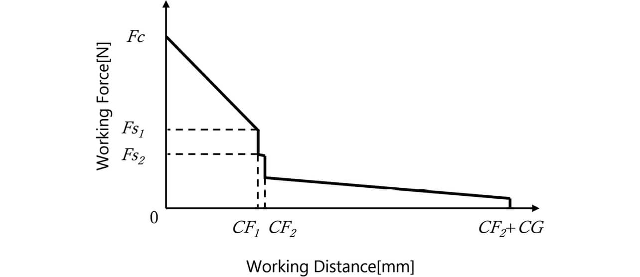
- Fc :
- Load [N] during ON state
- Fs1 :
- Load [N] at the instant of the opening of movable terminal 1
- Fs2 :
- Load [N] at the instant of the opening of movable terminal 2
- CF1 :
- Movable core system’s working travel [mm] until the transition from the ON state to the movable terminal 1 OPEN state (side with smaller CF)
- CF2 :
- Movable core system’s working travel [mm] until the transition from the ON state to the movable terminal 2 OPEN state (side with larger CF)
- CG :
- Movable core system’s working travel [mm] until the transition from the movable terminal 2 OPEN state to the OFF state
Of the two terminals that open at different times, the one with smaller CF is defined as CF1 and opens at an earlier time. Similarly to 3.2, the velocities v1i and v2i immediately before the times of contact opening of the CF1-side and CF2-side terminals were measured using a high-speed camera to calculate the impulses.
For the two movable terminals, Figs. 18 and 19 show graphs regarding CF1 and CF2, respectively: the horizontal axis represents the ratio of the measured value of CF1 or CF2 to the minimum design value for CF ; the vertical axis is the ratio representation of the impulse I given to the movable terminal corresponding to the applicable CF on the basis of the numerical values used in Section 3. Besides, the difference between CF1 and CF2 is a ratio difference and plotted with differentiation between small, medium, and large.
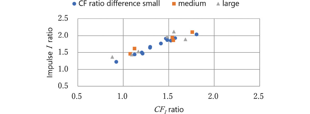
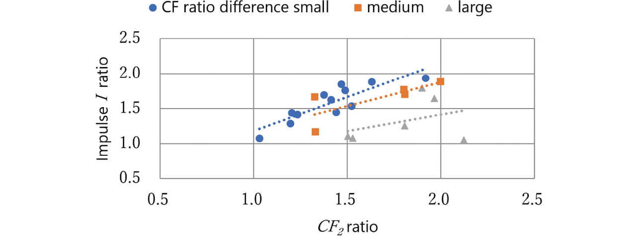
Fig. 18 reveals that the relationship between CF1 and impulse I remained unaffected by the CF ratio difference.
Meanwhile, Fig. 19 suggests that the CF2-side terminal tended to show lower and more varied colliding body’s impulses with larger CF ratio differences. The probable cause is that whereas the CF2-side terminal was affected by the collision of the preceding CF1-side terminal, the impacting body’s velocity decreased (but its impulse did not increase) with a larger CF ratio difference until the CF2-side terminal’s collision after the CF1-side terminal’s collision. These results confirm the following points regarding our double-break/twin-contact relay with a plunger-type mechanism:
- Besides the spring elastic energy explained in Section 3, the CF1-CF2 difference is an important design parameter for impulse.
- Our intended switching performance is achievable by designing the CF2 side with a smaller impulse I to give an impulse I ratio of 1 or larger for the consideration results in Section 3.
5. Conclusions
Following the capacity and efficiency enhancement of PV inverters used for photovoltaic power generation systems, their relays are also required to support high-capacity switching at high voltages and currents and heat generation suppression during large-current energization. We adopted pure Ag contacts for heat generation suppression and provided two parallel current-carrying paths inside our relay to achieve low contact resistance. Moreover, we empirically validated a mechanism that uses an impact designable based on the impulse calculated from the change in momentum to force open pure Ag contacts welded together at electrical switching. Incorporating these consideration results into our switching mechanism, we developed Model G9KA as a practically viable PV inverter relay boasting the lowest contact resistance and highest capacity switching among our lineup of high-capacity power relays.
Under real-use conditions, the switching mechanism may be affected by the presence and type of diodes for preventing counter-electromotive voltage in the coil drive or the relay’s own installation directivity. However, a threshold determined by our approach enables a design with such factors taken into account.
Bearing in mind also relays other than plunger-type ones, we will tackle calculating the forced opening force required for various forms of welded contacts in complex switching behavior and continue developing relay products for safe and stable energization/interruption toward more widespread use of renewable energy.
References
- 1)
- K. Mano, Reliability of Contact Parts. Third Ed., (in Japanese), Tokyo, Sogo Denshi Shuppan, 1981, 303 p., 3055-20133-2213.
- 2)
- S. Sawada, K. Shimizu, S. Shimada, and Y. Hattori, “Prediction of Electrical Contact Resistance of Tin or Silver Plating,” (in Japanese), SEI Technical Review, no. 177, July issue, pp. 36-42, 2010.
- 3)
- H. Aichi, T. Matsumura, and I. Miyachi, “Characteristics of Contact Resistance for Ag, Cu and Al Spot Contact under DC Current Flow of 300 A,” (in Japanese), IEEJ Transactions B, vol. 118, no.7-8, pp. 825-830, 1998.
- 4)
- S. Asai and J. Sekikawa, “Contact Resistance in Silver Contact Pair Applications - Load Characteristics Measurement,” (in Japanese) presented at RE-SECCT, 2017, No. 203-2.
- 5)
- S. Koide, Physics. 35th Ed., (in Japanese), Tokyo, Shokabo, 1990, 378 p., 4-7853-2019-2.
The names of products in the text may be trademarks of each company.