


A Small and Light 3D Vision Sensor for Robot Arms with Robustness in Factory Automation
- 3D sensor
- Robot picking
- For robot arms
- Small and light
- With robustness
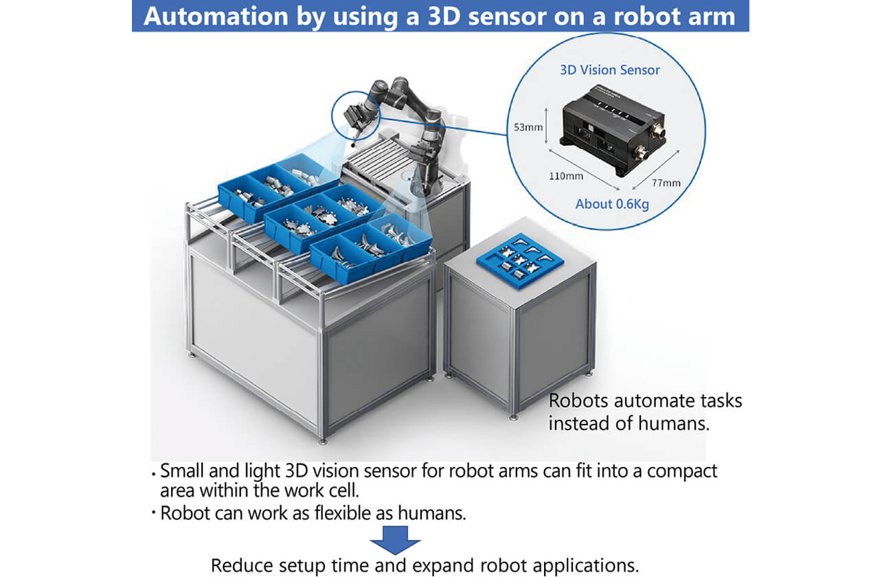
In the manufacturing industry, automation of manufacturing, especially the introduction of robots, is being actively promoted because of labor shortages and rising labor costs, but installation space, start-up person-hours, and flexibility at work are issues to be addressed. In particular, a 3D sensor is essential to estimating the position and orientation of parts accurately in bin picking applications, and a robot hand-mounted 3D sensor is required to solve the problems. One of the requirements for a sensor mounted on a robot hand is that it be small and light, but the most conventional 3D sensors are large and heavy because of their measurement methods. Therefore, we developed a robot hand-mounted 3D sensor with a height of 53 mm × width of 110 mm × depth of 77 mm and a weight of 570 g by developing an optimal measurement method and a simple optical system. Furthermore, to reduce measurement errors caused by ambient temperature changes at the manufacturing site, we employed a method to control the temperature of the optical system at a constant level using heaters. Experiments confirmed that the measurement error of the distance value in the temperature change from 0°C to 40°C was within 1 mm.
1. Introduction
In recent years, as the situation where the issues of labor shortages and rising labor costs increase in severity in the manufacturing industry, then automation of assembly, inspection and carrying processes that essentially require experience, and a sense of and reliance on humans are urgent needs. In addition, the improvement of productivity by substituting machines (robots) for human work is increasingly demanded at manufacturing sites. For example, in order to introduce robots in processes for bin picking so far performed by humans, a 3D vision sensor (hereafter 3D sensor) capable of correctly measuring and recognizing parts is essential. A 2D camera obtains only two-dimensional vertical and horizontal information from planar images. On the other hand, since a 3D sensor can obtain not only vertical and horizontal information but also distance information, it can recognize the three-dimensional position and posture of parts.
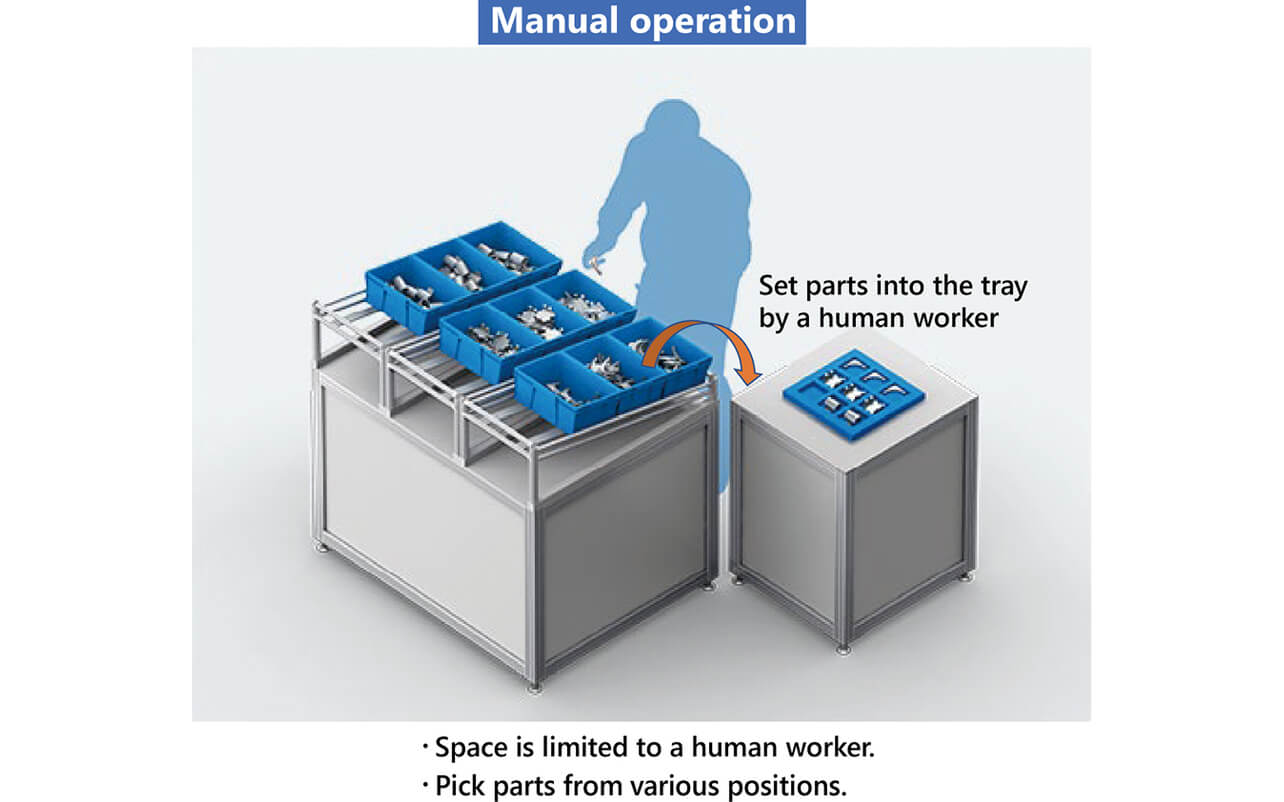
In addition, installation space, start-up person-hours, and flexibility at work should be considered in the introduction of robots to the manufacturing site, resulting in an obstacle to introduction. When introducing robots into the space for human work, installation space is limited. Reduction in the start-up person-hours as the time spent for installation and adjustment of robots and sensors is desired. Furthermore, flexibility at work is required in order to address setup changes and parts placed in various positions. The 3D sensors used at the manufacturing site are the fixed type and robot hand-mounted type (hereafter hand-mounted type). Installation of a fixed type sensor requires a large-scale dedicated installation facility. Moreover, since the measurement area is fixed depending on the installation position and posture, the adjustment of the sensor installation position takes time, and it is difficult to flexibly address process changes, such as setup changes. On the other hand, the hand-mounted type has an advantage that a simple installation jig can be installed to a robot, and the movement of the robot hand enables the free change of position and posture of the sensor. Therefore, the hand-mounted type is expected to attract much attention as the form for solving the three obstacles when introducing the above robots. Fig. 1 is an example of work so far performed by humans, and Fig. 2 is a view of automation. We aimed to improve the productivity of the customer by introducing robots into the production sites; we developed a 3D sensor that can be mounted on a robot hand.
2. Three-dimensional Measurement Principle and 3D Sensor Utilized at Manufacturing Sites
2.1 Comparison of Three-dimensional Measurement Principle
There are various techniques for three-dimensional measurements1). Fig. 3 shows a chart in which the three-dimensional principle is arranged.
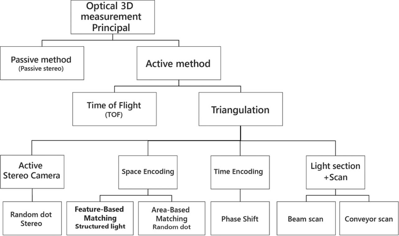
The principle of three-dimensional measurement is roughly classified into an active method in which the measurement is performed by projecting measurement light and a passive method not requiring the measurement light. The passive method performs three-dimensional measurement from an image obtained based on environmental light without using a measurement light. Therefore, it has the disadvantage that the measurement is easily disabled because of the influence of environmental light, and measurement error easily increases. The active methods can be classified into a time of flight method (hereafter TOF method) and triangulation. The TOF method calculates the distance value from the time between the reflection of projected light on an object to be measured and the light received by an image pickup device, and parts placed in bulk easily cause measurement errors due to the repetitive reflection of measurement light between the parts (reciprocal reflection). In addition, it has the disadvantage that the measurement of travel time of extremely high-speed light deteriorates measurement accuracy in short distances. On the other hand, since the measurement accuracy of triangulation is higher because the distance is shorter, in principle, it can measure at high accuracy in the robot picking environment where a sensor is used in a comparatively short distance (within about 1 m). From the above description, triangulation is suitable for the 3D sensor for robot picking.
2.2 Conventional 3D Sensor Used at Manufacturing Sites
Since the measurable area of a light section method among triangulation is linear, it is necessary to provide the light projection section with a scanning function or provide a mechanism for moving an object to perform the three-dimensional measurement. Reliability is an issue because a moving section is needed to provide the light projection section with the scanning function. In addition, there is a problem that correct measurement is difficult because the position of objects shifts when the objects placed in bulk are moved by a conveyor. A space encoding method has the problem that the distortion of patterns projected to an object causes a measurement error. Therefore, a time encoding method represented by a phase shift method and a 3D sensor for an active stereo camera have been mainly used at manufacturing sites.
3. Problem for Realizing Hand-Mounted 3D Sensor
3.1 Requirement for Hand-mounted 3D Sensor
The 3D sensor is often installed to the comparatively end side of the robot hand in order to avoid the visual field from being obstructed by the robot hand to be mounted when the robot hand is mounted with a 3D sensor. Therefore, when using a large-size sensor, there is a higher possibility that the sensor interferes with a container having parts at the time of picking parts. In addition, a small-size robot represented by a cooperative robot often has a low portable weight. Therefore, if a sensor is heavy, there is the possibility that the sensor cannot be mounted on the robot hand because the portable weight is exceeded, and parts picking is impossible because the weight of the sensor and the parts exceeds the portable weight. From the above, the small size and light weight of the 3D sensor to be mounted on the robot hand are required. In addition, there is a case that the robot is used in the environment where the temperature greatly changes, for example, in a semi-outdoor place or in a place close to machining equipment depending on the manufacturing site. The 3D sensor is required to have environmental resistance so that it performs measurements with measurement errors within several millimeters in order to perform parts picking accurately even in such an environment without affecting productivity.
3.2 Problem of Conventional 3D Sensor
Since the time encoding method having been adopted by conventional 3D sensors requires multiple images with different patterns projected for measurements, a projector mounted on the sensor should have a function for switching patterns, and a complicated optical system is required. An active stereo camera requires at least two cameras and one projector. As mentioned above, since the time encoding method and the active stereo camera consist of many parts, sensors easily became large and heavy. In addition, since the measurement principle of both the above methods is triangulation, when the change of the parts dimension or fluctuation of the optical parameter occurred because of the temperature change of the sensor, the customer was required to stop the process at the manufacturing site to execute calibration to maintain measurement accuracy, leading to lower productivity. The above problem made it difficult to realize hand-mounted 3D sensors in the conventional measuring method.
4. Technology for Solving Problem
To solve the above problem, the following two points were examined:
4.1 Measurement Principle for Realizing Small and Light Structure
In order to realize a small and light structure, it is necessary to make the optical system simple. A 3D measurement system that does not require switching the pattern to be projected is suitable for this. Thus, we adopted the space encoding method that can measure with a single projection pattern as a 3D measuring method.
The space encoding method is a system that calculates the distance value by projecting a pattern to an object to obtain an image, analyzing it to identify the correspondence between the projector and the camera (which pixel of projector corresponds to which pixel of camera to form image), and then performs triangulation. There is an area-based matching method (template matching method) and a feature-based matching method as techniques for identifying the correspondence between the projector and the camera. The area-based matching method uses a random pattern, and the feature-based matching method uses a pattern embedded with feature points in order to identify correspondence. We adopted the feature-based matching method with features comparatively robust to contrast reduction and image distortion. The composition of the pattern is shown in Fig. 4. The pattern was composed by combining four types of minimum unit pattern. The minimum unit pattern is composed of small rectangular S1 in the central position and large rectangular S2.
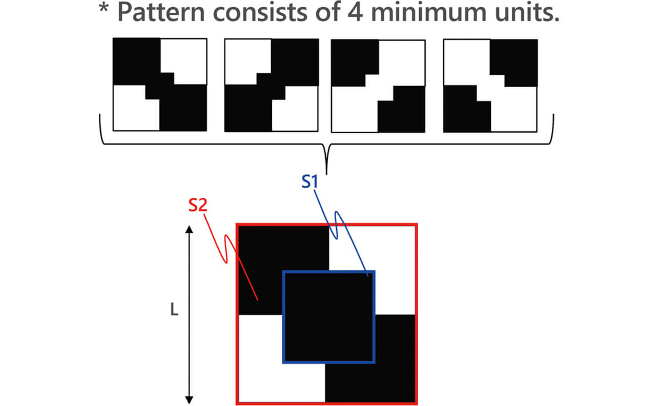
Fig. 5 shows examples of the pattern examined. Ratio of sizes S1/S2 of area S1 and area S2 in the minimum unit pattern and the minimum pattern size L were assumed to be design parameters. The parameters were optimized by simulating the contrast reduction and pattern distortion generated when being projected onto a workpiece for these patterns and aiming for the coexistence of space resolution and measurement stability.
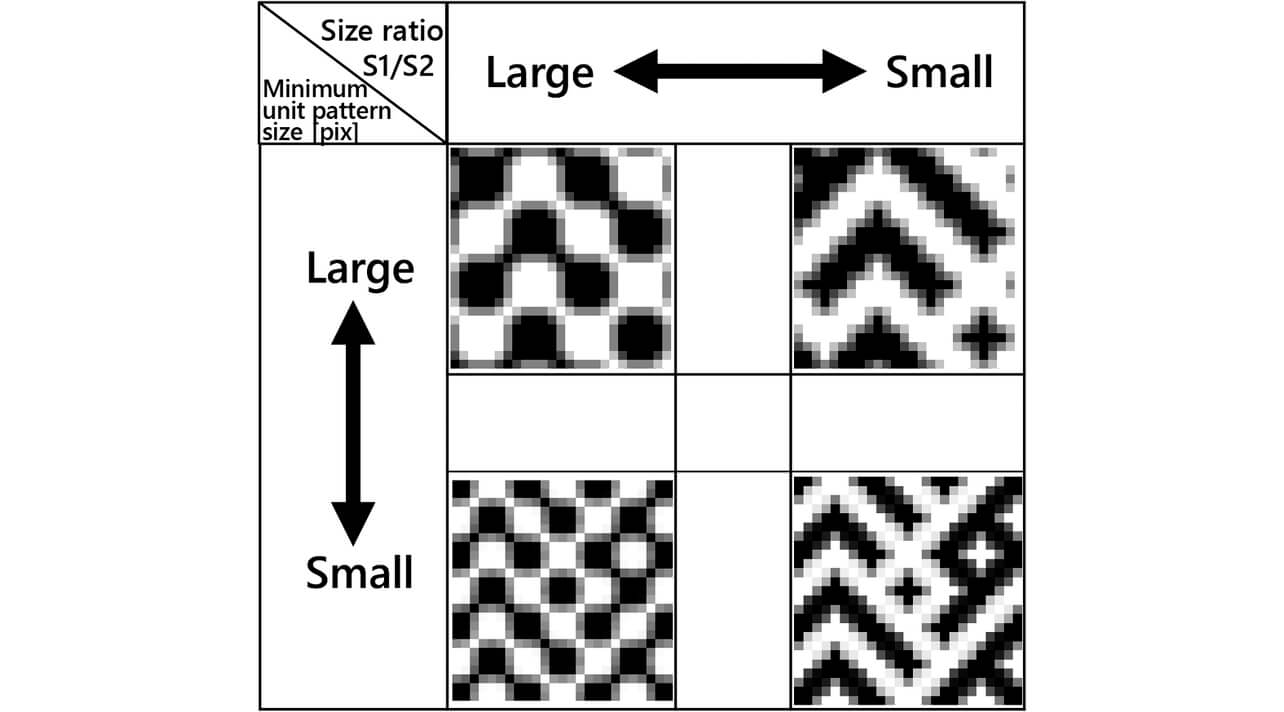
Fig. 6 shows the created pattern.

4.2 Structure Realizing Stable Measurement even if Environmental Temperature Changes
In triangulation, the distance value (measured value Z ) is expressed by formula (1).

where b is the length of the base line (distance between camera and projector), f is the focal distance of the lens, and D is the parallax between the camera and projector. Since the length of the base line, especially the focal distance of the lens, is a parameter that fluctuates from temperature changes, the measured value Z changes depending on the temperature. In addition, since the geometrical arrangement of the optical system shifts with a temperature change, parallax D also fluctuates from a temperature change. From the above, it is found that measurement error due to temperature changes can be suppressed by making the ambient temperature of the optical system constant. Thus, we examined the structure for keeping the temperature of the optical system, especially of the lens, constant. Fig. 7 shows the structure of the camera.
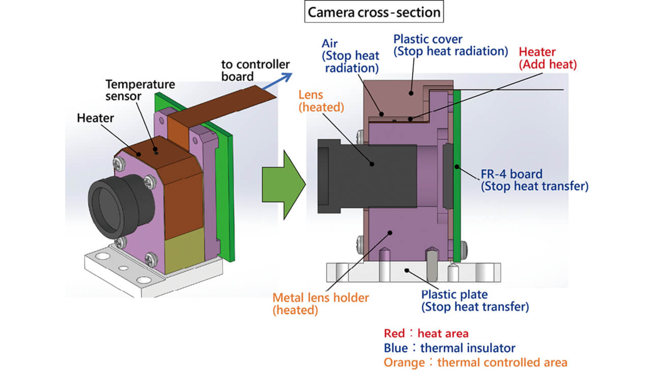
A film heater was adopted from the viewpoint of small size and light weight in order to heat the lens holder for holding the lens, and a temperature sensor was mounted on the heater for monitoring temperature. The calorific value was controlled corresponding to the change in the environmental temperature so as to make the temperature of the lens constant. Since heat is dissipated through the housing even if the lens holder is heated, the calorific value of the heater becomes insufficient, especially when the environmental temperature is low. In order to increase heater output, there is a problem that the increase in the power supply circuit scale and the increase in the print circuit board size lead to cost increases because more power is required. Thus, we adopted a thermal insulation structure that stops heat transfer and heat radiation and cuts off the heat dissipation path from the lens holder so as to avoid heat from escaping.
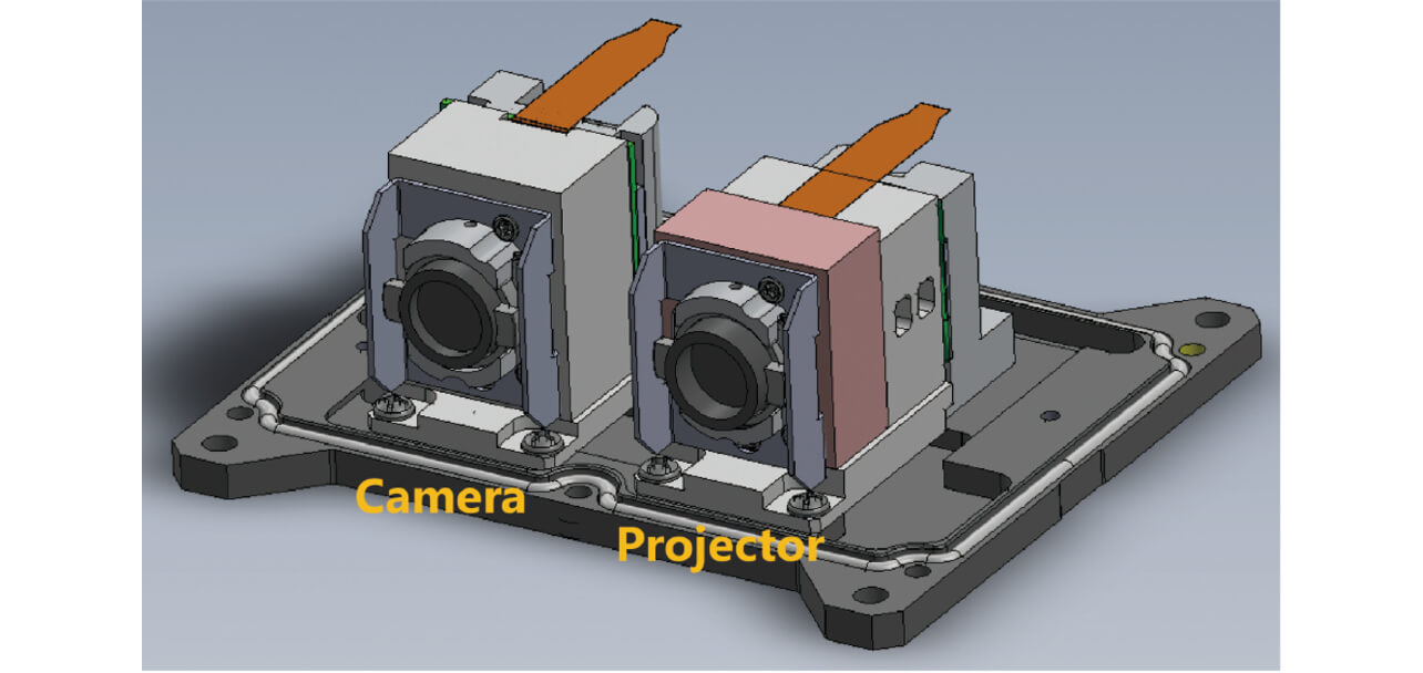
Considering the above, we realized a 3D sensor that can perform stable measurement even in the environment at the manufacturing site while limiting the size and weight to a level capable of mounting on the hand. Fig. 8 shows the structure of the sensor. The size of the housing is 53 mm high × 110 mm wide × 77 mm deep, and approx. 570 g in weight.
5. Evaluation Experiment
5.1 3 D Measurement Evaluation in Space Encoding Method
Fig. 9 shows the point cloud display results measured by the 3D sensor (feature-based matching method) that adopted the created patterns. In order to compare, the three-dimensional point cloud display results of the sensor (area-based matching method) using random dot patterns are shown. The object is an office chair.
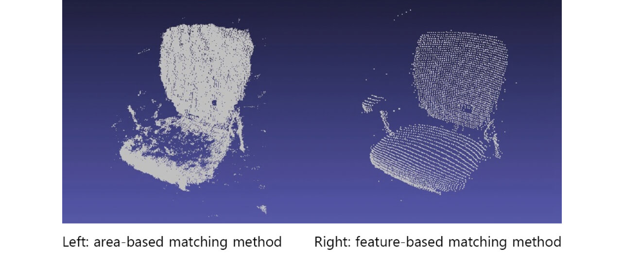
The results show that there is an area where the area-based matching method could not measure the seat surface of the object. This is because the measurement failed because of the distortion of the random dot pattern by the fine unevenness of the seat surface of the object. In addition, the measured value is transmitted even from the place where the object does not exist, meaning erroneous measurement. On the other hand, the feature-based matching method measured comparatively correctly because this method was not influenced by distortion of the pattern.
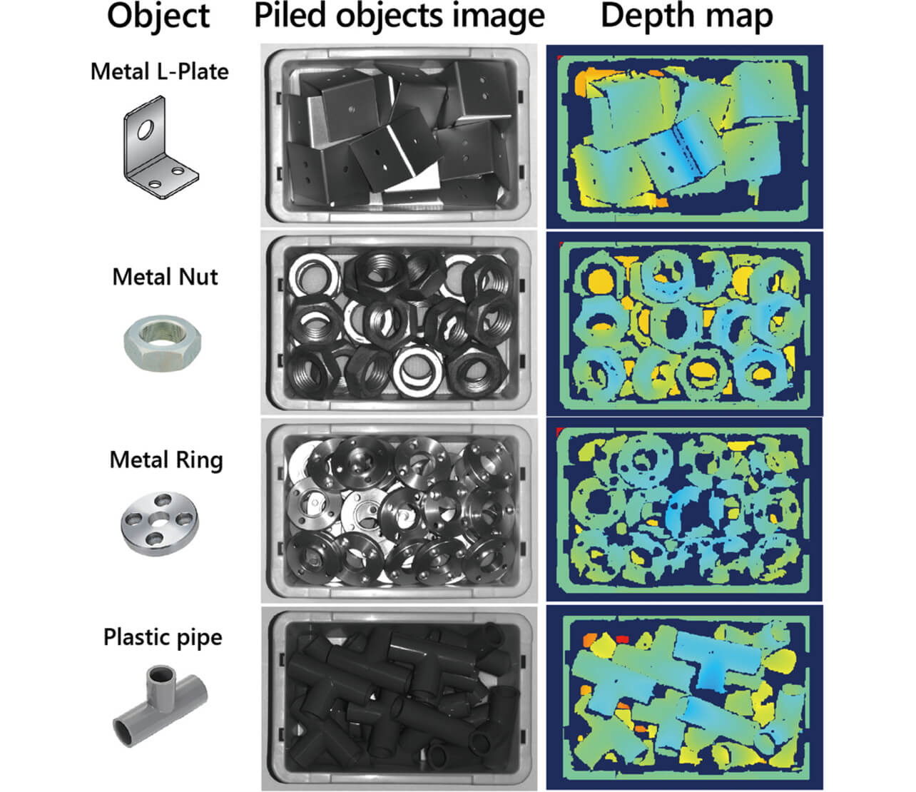
From the above, it was found that the feature-based matching method adopted by this development can perform stable measurements with higher accuracy. Fig. 10 shows the distance image display results when various parts were measured using the developed 3D sensor. Distance images of various parts placed in bulk can be obtained, and the position and posture of parts are recognized.
5.2 Evaluation of Measurement Error due to Temperature Change
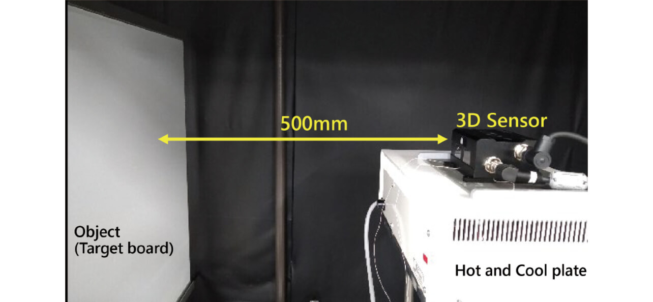
Measurement errors were evaluated by installing a developed prototype 3D sensor on the equipment capable of controlling the temperature of the plate surface (Cool Plate NCP-2215 manufactured by Nissin Rika Co., specification temperature range-5°C to 80°C) and setting the plate temperature at 0°C, 20°C, and 40°C. Fig. 11 shows the evaluation system.
Evaluations were performed in cases with and without implementation of heater control, and the effect of heater control was verified. The average of the distance values of 100 × 100 points at the end of the measurement field where the measurement error is largest was recorded, and errors in the distance value were calculated assuming the distance value at an environment temperature of 0°C as the reference value. Fig. 12 shows the evaluation results.
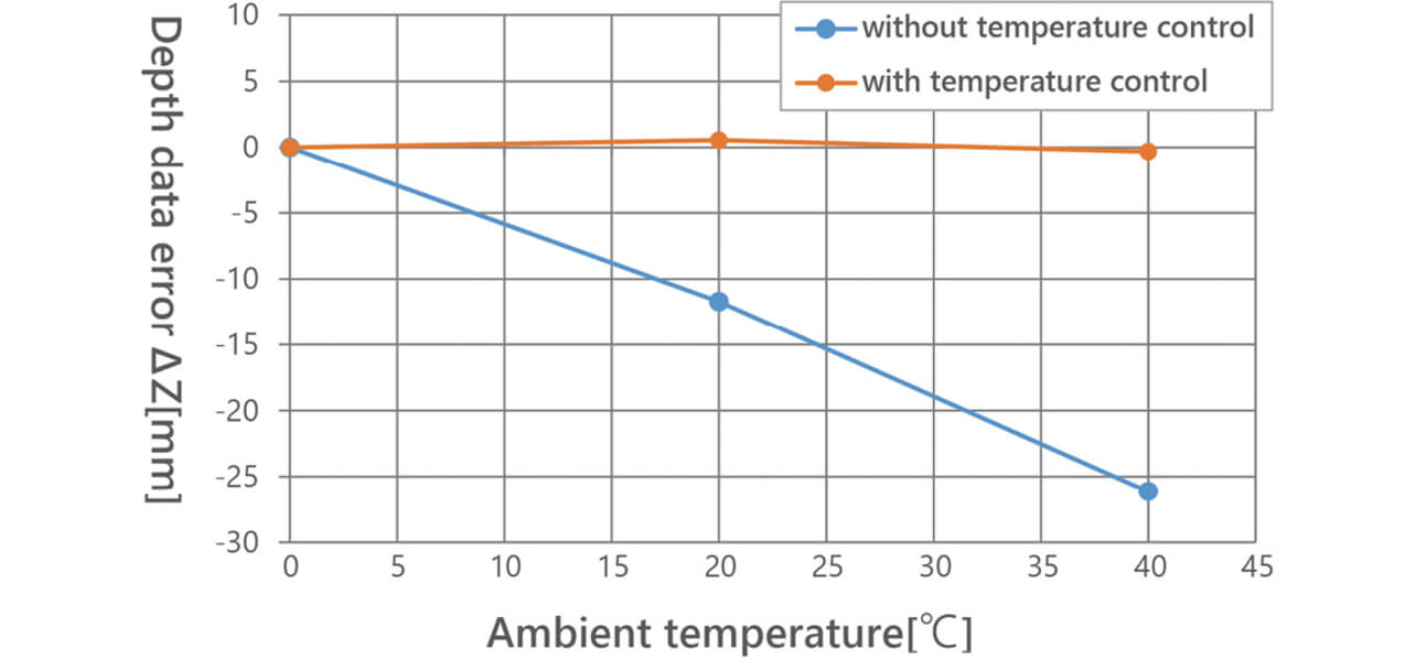
We verified that measurement error ΔZ of the distance value exceeds 20 mm at the environment temperatures of 0°C to 40°C without temperature control, while the error can be suppressed within 1 mm with temperature control. From the above, we recognized that control of the lens temperature at a constant value can greatly reduce measurement error.
6. Conclusion
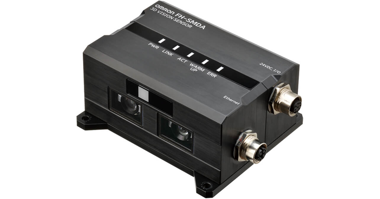
For the problems of the installation space for 3D sensors, start-up person-hours, and flexibility of work that were obstacles for the introduction of robots at the manufacturing site, we developed a small, light 3D sensor that could be mounted on a robot hand. The selection of the optimum measurement principle and the design of a simple optical system projector realized a small, light structure with the dimensions of 53 mm high × 110 mm wide × 77 mm deep and with a weight of approx. 570 g. In addition, we verified the use of a prototype sensor where the measurement error for distance when the environment temperature changed by 40°C could be suppressed within 1 mm by temperature control of the optical system regarding the influence of temperature changes on the manufacturing site. We commercially released the 3D Sensor Type FH-SMDA-GS050 applied with this technology on March 2021. Fig. 13 shows the appearance of the 3D sensor.
We also desire to hereinafter continue the development of technology for realizing further size and weight reductions while maintaining high-speed and high accuracy to contribute to the improvement of productivity at the manufacturing site of the customer.
References
- 1)
- J. Geng, “Structured-light 3D surface imaging: a tutorial,” Adv. Opt. Photonics, vol. 3, no. 2, pp. 128-160, 2011.
The names of products in the text may be trademarks of each company.