


Safety Design Method for Interactive Manufacturing System
- Interactive
- Interactive manufacturing system
- Machinery safety
- Risk assessment
- Safety
Various interactive manufacturing systems are developing to enable humans and robots to produce products in cooperation. For safety designers who design the safety of interactive manufacturing systems face difficulties to select a practical safety design method. The origin of this issue is a lack of appropriate safety standards for references.
Determination measures of risk reduction against identified risks are also challenging to set the criteria for interactive manufacturing system. It leads to increased cost and decreased usability of the interactive manufacturing systems and the inability to prove the safety design’s validity.
This paper reports on a new method for the efficient safety design of an interactive manufacturing system is studied and its effectiveness is verified. First, applications of the interactive manufacturing systems were analyzed and a new concept of consecutive application was created. Then, by applying this concept, a method was devised to select the most appropriate safety criteria as a basis for safety design. Furthermore, a method for systematic hazard identification and determination of the need for risk reduction was studied and its effectiveness was confirmed.
By applying these methods, designers can demonstrate safety of the interactive manufacturing system that adequate cost and user-friendly system.
1. Introduction
The environment surrounding the manufacturing industry is changing hour to hour in response to innovations in manufacturing technology or the trends in the increasingly diversified global society. OMRON has proposed a cell line control system (CLCS) as an example of a new manufacturing system adapted to the change. A CLCS is a cell line equipped with a production control mechanism and an information platform for producing non-defective products most efficiently in multi-product variable-volume production. Included among such CLCSs are human-machine collaborative, interactive manufacturing systems in which an industrial robot (cobot) is placed in the same cell as an operator to operate in sync with the human in a human-machine shared workspace.
For human-machine collaborative, interactive manufacturing systems, the concept of workers’ safety assurance also needs updating. The conventional concept of safety dictates, as a general rule, that human and machine workspaces be clearly divided with physical guards or other safety dividers. Conversely, interactive manufacturing systems are required to provide high safety and production efficiency in a human-machine shared workspace.
When it comes to building safety into a manufacturing system, it is rational to rely on ISO or other international safety standards for the system’s design. However, two challenges lie ahead for developing a safety design of a cobot-based interactive manufacturing system. One challenge is excess safety designs due to the mismatch between the application of the cobot-based interactive manufacturing system and the applications assumed by the international safety standards for industrial robots. This challenge leads to an increased equipment cost and reduced user-friendliness. The other challenge relates to hazard identification in the interactive manufacturing system. Hazards must be systematically identified, and consideration must be made regarding the necessity of risk reduction for identified hazards. The problem is the lack of criteria for determining the scope of the risk reduction measures to be implemented. Hence, a determination thus made will inevitably be dependent on the designer’s sense, posing an inability to ensure accountability for user safety.
We first analyzed an interactive manufacturing system application and created a novel concept of consecutive application to solve the above problems. Based on this new concept, we developed a method of designing new interactive manufacturing systems without being unreasonably restricted by any specific standards. Besides, we considered a method for systematically identifying hazards and logically determining the necessity of risk reduction measures and put the method to actual applications to verify its effectiveness. These solutions will allow designers to optimize the safety design of interactive manufacturing systems, independently of the existing standards, and make an objective explanation of the safety design. Moreover, these solutions will help reduce design costs and deliver flexible equipment safety designs.
2. Safety design and safety standards for interactive manufacturing systems
2.1 Current state of safety design for interactive manufacturing systems
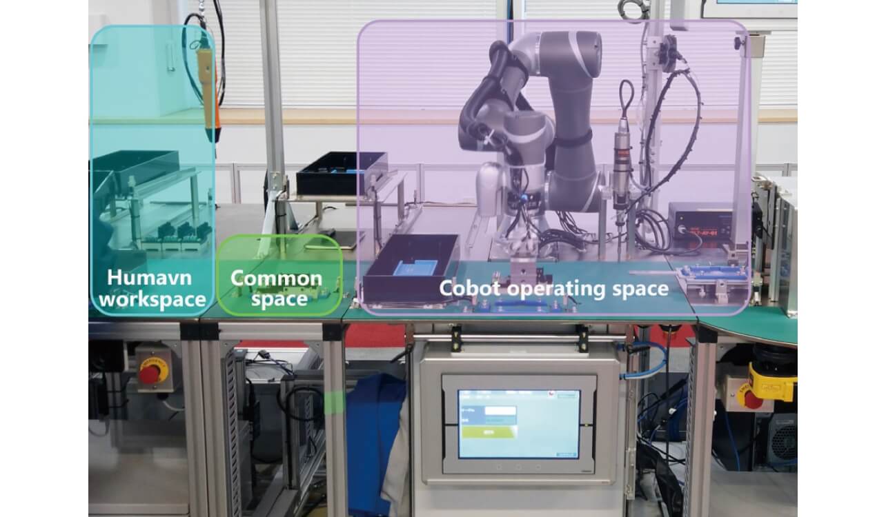
The CLCS of our interest is an interactive manufacturing system in which an industrial robot (cobot) is placed in the same cell as an operator to operate in sync with the person in a human-machine shared workspace. This CLCS is intended as a cell line that works as an integrated whole to complete a series of steps through human-machine interaction while allowing the operator and the cobot to perform such tasks as assembly, screw fastening, laser marking, and inspection on workpieces independently from each other as explained in Table 1. These tasks are sequentially performed as workpieces move from left to right through the three spaces as shown in Fig. 1. A CLCS that gets tasks done through human-machine collaboration in this way is called a collaborative CLCS.
| Step | Task content | Task execution space |
|---|---|---|
| Step 1 | The operator performs the workpiece assembly task according to the standard operating procedures. | Operator’s workspace |
| Step 2 | The operator sets the assembled workpiece in the shared space in front of the cobot and hands it over to the cobot. | Shared space |
| Step 3 | The cobot grips and moves the workpiece set in the shared space to the cobot’s workspace. | Shared space |
| Step 4 | The cobot performs the screw-fastening task on the workpiece moved to the cobot’s workspace. | Cobot’s workspace |
| Step 5 | After completing the screw-fastening step, the cobot loads the workpiece into the laser marking unit for the next step. | Cobot’s workspace |
| Step 6 | From this step on, another cobot performs the takeout, inspection, and ejection tasks for workpieces from the laser marking unit. | Cobot’s workspace |
Interactive manufacturing systems, including collaborative CLCSs, assume human-machine workspace sharing. A typical example of such applications is collaborative operation as defined in ISO/TS 150661), an international standard for cobot applications. A collaborative operation system consists of a collaborative workspace for a cobot and an operator to simultaneously perform their tasks and an operating space for the cobot to operate independently. This paper calls such a system a collaborative application system.
Unless needed otherwise, a designer using a cobot will usually regard any cobot-based application as a collaborative application. As the safety design standard to be applied, the designer will adopt either ISO/TS 15066 or ISO 10218-22); the latter is a safety standard for industrial robot systems. However, the requirements specified in these standards apply to collaborative applications. Therefore, for interactive manufacturing systems that, as with collaborative CLCSs, use a cobot, which operates collaboratively with an operator while performing an independent task from the operator’s one, it would be problematic in terms of cost and user-friendliness to attempt to develop a design meeting these two safety standards. More specifically, if the requirements of these safety standards are strictly applied, many safety features must be adopted, pushing up the cost involved in safety feature development. Besides, these safety features would pose additional causes of cobot’s stoppage, giving rise to the need for frequent reset operations and leading to reduced user-friendliness.
2.2 Differences between collaborative CLCS applications and collaborative applications
This section describes the application analysis performed from the perspective of the step/task execution spaces in interactive manufacturing systems to determine whether ISO/TS 15066 can be applied to all cobot-based interactive manufacturing systems. The analysis aimed at clarifying the inclusion or non-inclusion of collaborative operations as the criteria for the applicability of the existing standards.
First, from among the Steps/Tasks 1) to 6) in Table 1, we identified ones in which the human and the machine (cobot) come into each other’s proximity. The steps with the shortest distance between the human and the machine (cobot) are Steps 2) and 3), between which workpieces are handed over. These steps are performed by the operator setting a workpiece in the shared space provided between the operator’s workspace and the cobot’s workspace and then by the cobot moving to grip the workpiece. In this sequence of events, the cobot’s action starts at the trigger of the workpiece placement in a predetermined location within the shared space. Hence, the operator’s workpiece setting task and the cobot’s workpiece gripping task do not occur simultaneously. It follows then that no collaborative operations are involved, which are specified in the two safety standards for industrial robots mentioned in Subsection 2.1 as ones in which an operator and a cobot perform tasks simultaneously in a shared space. Thus, the application under consideration right here cannot be found among collaborative applications. As a result, it has become clear that safety designs not based on ISO/TS 15066 can be adopted for collaborative CLCSs, which constitute a new class of interactive manufacturing systems different than collaborative applications.
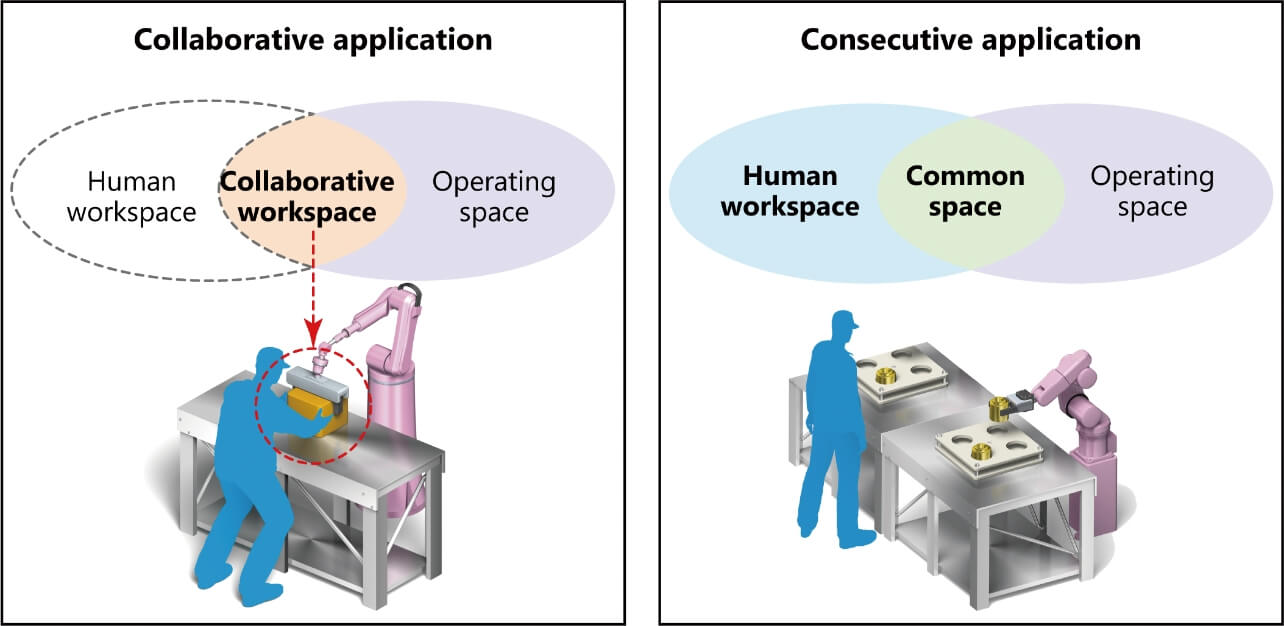
Such a new interactive manufacturing system application can be defined as ones consisting of the three spaces shown in Fig. 1: an operator’s workspace, a shared space for workpiece handover from the operator to the cobot, and a cobot’s workspace. This paper hereafter refers to these three spaces as the human workspace, the common space, and the operating space, respectively, and calls an application of a manufacturing system consisting of the three spaces a consecutive application. The differences in spatial composition between this consecutive application and the collaborative applications described in Subsection 2.1 can be shown as in Fig. 2.
2.3 Safety standards suitable for interactive manufacturing system applications
As explained in Subsections 2.1 and 2.2, interactive manufacturing systems can be classified into either collaborative or consecutive applications, depending on their application’s characteristics. Their comparison can be summarized as in Table 2.
| Classification criterion | Interactive Manufacturing System (e.g.: collaborative CLCS) | |
|---|---|---|
| Collaborative application | Consecutive application | |
| Means of human-machine physical separation | Not included | Not included |
| Use of a cobot | Required | Optional |
| Concurrent human and machine tasks | Included | Not included |
| Human-machine shared workspace | Collaborative Workspace | Common Space |
| Individual machinery safety standards (C standards) | ISO 10218-2, ISO/TS 15066 |
N/A |
No interactive manufacturing systems include any means of human-machine physical separation because they get tasks done through human-machine collaboration. Nevertheless, the space these systems include for task execution through human-machine collaboration can be classified, depending on the task’s characteristics, as either a collaborative workspace or a common space. The distinction between these spaces serves as the determining factor for the usability of the existing individual machinery safety standards as safety design guidelines. A collaborative application involves a cobot and an operator performing their respective tasks simultaneously in a shared space. Hence, its safety can be evaluated based on a specific product safety standard for industrial robots.
Meanwhile, a consecutive application produces a product through human-machine interaction but with no tasks performed simultaneously in a shared space: the machine that operates in conjunction with the operator is not limited to a cobot. Therefore, a proper safety design for a consecutive application is unachievable with the requirements of existing individual machinery safety standards.
Table 2 above shows the focal points of the application analysis performed to design an interactive manufacturing system. This table helps to select an appropriate reference standard. The table serves as a method of explicitly showing that some applications, even cobot-based ones, fall outside the scope of ISO 10218-2 or ISO/TS 15066. Thus, Table 2 is useful to avoid excess safety designs due to unrealistic safety requirements in these standards.
3. Risk assessment for interactive manufacturing systems
3.1 Current state of hazard identification for interactive manufacturing systems
A collaborative CLCS is a system equipped with no physical guards or other safety dividers between the human and the machine (cobot) and allows easier access to hazards than conventional manufacturing systems equipped with physical means of protection. Thus, this system is prone to accidental entry of the operator or body parts into its machine operating area. Therefore, it needs a risk assessment that considers hazardous situations due to such erroneous human behaviors, in other words, misuse.
A manufacturing system risk assessment must assume various accident scenarios involving misuse and exhaustively identify all hazards to consider a broad range of risks from the early stage of design3). However, with overconcentration on exhaustive hazard identification, excessive energies are often poured into assuming too many accident scenarios that include hazardous events hardly likely to occur in reality or misuses that can occur only under very limited conditions.
Moreover, though supposed to be performed preferably by a team of members with diverse experience and knowledge4), in practice, risk assessment is often performed only by a specific kind of person, such as personnel responsible for the manufacturing system design. It is considered problematic that the accuracy of the range of possible misuses thus assumed varies depending on the personnel’s experience and other qualities. Besides, for the misuses assumed through hazard identification, if they are reasonably foreseeable, preventive measures against them must be implemented by design. However, ISO 12100 and other international safety standards specify no criteria for determining reasonable foreseeability, leaving the determination to individual designers’ design sense. Still, if accident scenario assumptions are randomly made with quantity over quality, or if misuse consideration relies entirely on personal experience and imagination, or if risk reduction necessity is determined based on personal sense, the assumptions, consideration, and determination thus made will be biased in coverage and evidence. Such biases will eventually lead to overlooked serious hazards or insufficiently reduced risks. Situations of this kind have already caused a real problem of the inability to ensure accountability for user safety.
Accordingly, we focused our attention on the space categories presented in Section 2 and the categories of erroneous human behaviors to work out a solution to such problems.
3.2 Risk reduction necessity determination method using systematic hazard identification and misuse analysis
First, we considered a method for systematically identifying hazards due to erroneous human behaviors. The causes of human behaviors leading to hazardous situations fall into four categories, as in Categories a to d of Fig. 35,6). Using as a clue this four-way classification of human behaviors, we took into account human involvements in hazards in the collaborative CLCS spaces and human behaviors therein to consider accident scenarios.
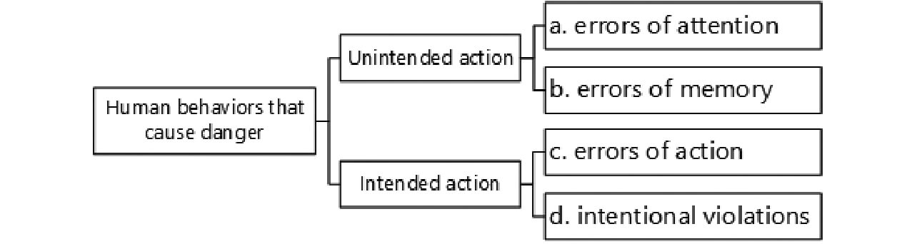
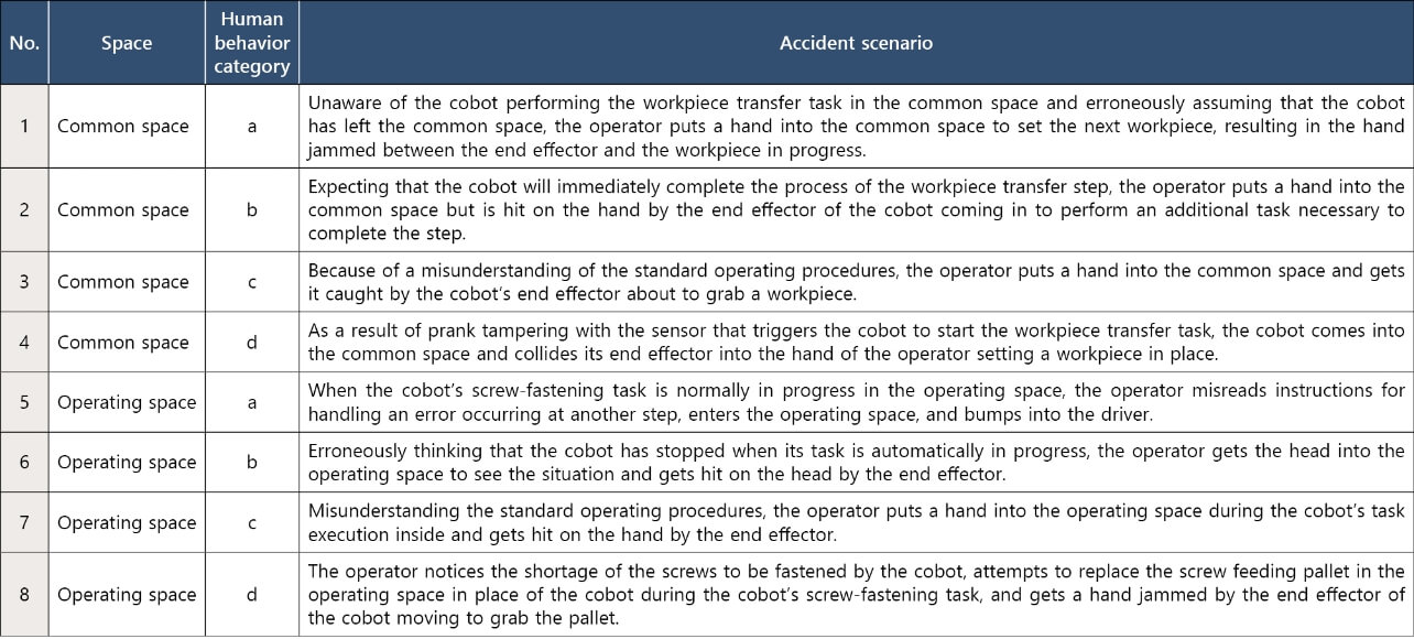
Table 3 considers accident scenarios due to collaborative CLCS-related human behaviors for the Common and Operating Spaces for the machine (cobot) to perform tasks and matches these scenarios with Categories a to d of human behaviors leading to hazardous situations. In this table, Scenarios Nos. 1 to 4 are accident scenarios due to entry of the operator or body parts into the common space despite the machine (cobot) installed therein. Meanwhile, Scenarios Nos. 5 to 8 are accident scenarios due to the entry of the operator or body parts into the operating space with the cobot in action.
Then, we performed a risk reduction necessity determination analysis for the accident scenarios due to human misuse from Table 3. As explained in Subsection 3.1, to determine whether the misuse requires reduced risk, an analyst must determine whether the misuse is reasonably foreseeable. We examined this process and represented it into a flowchart shown in Fig. 4. If judged by this flowchart as reasonably foreseeable, the misuse can be determined as one for which the part up to risk reduction must be performed via the subsequent flow that includes risk estimation. Otherwise, no risk reduction will be required. In the latter case, the analyst can terminate the misuse analysis by recording the obtained determination results.
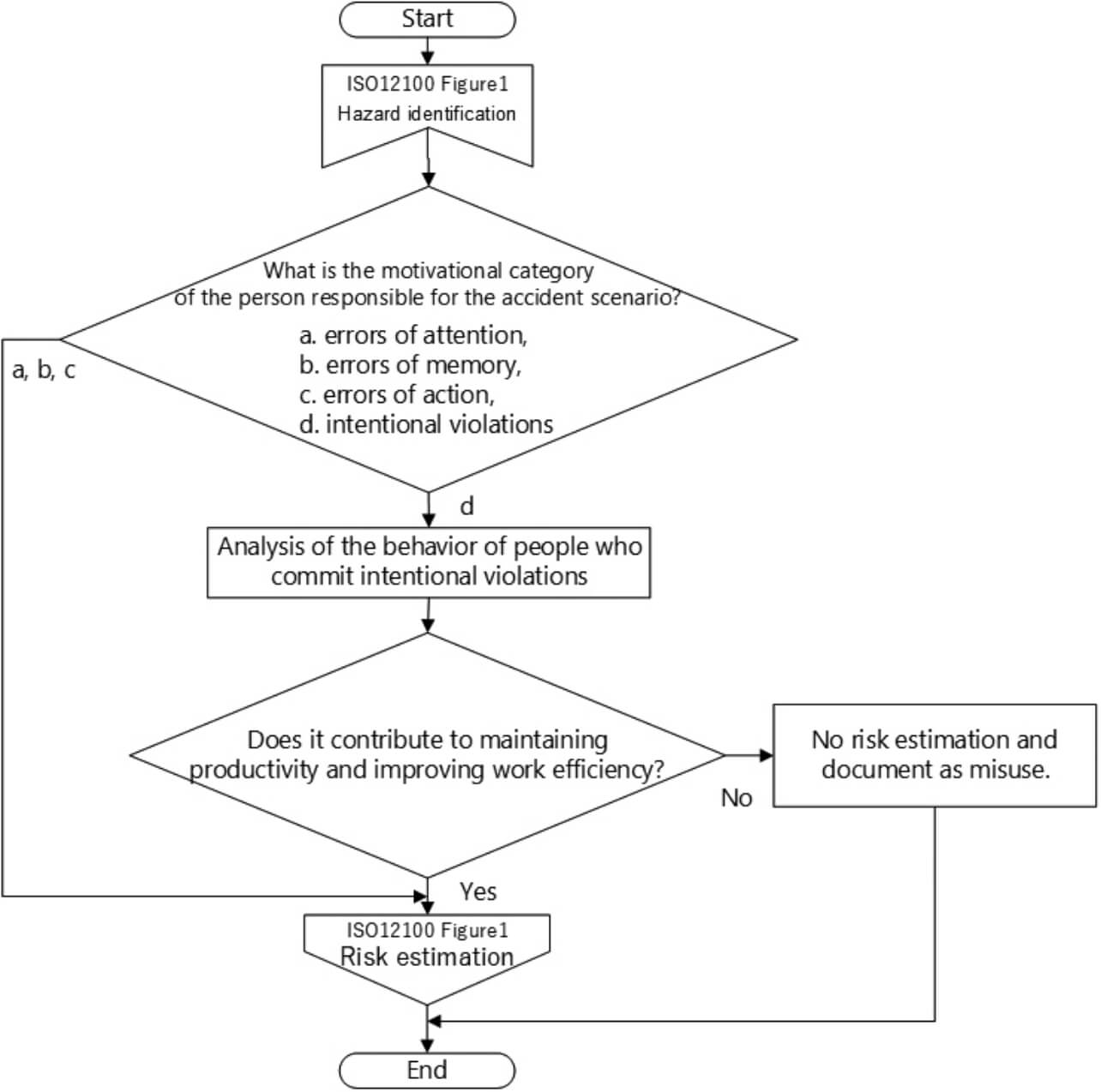
Judgment criteria are presented below based on individuals’ motivations leading to accident scenarios. Unintended human actions, such as Category-a “Slips” or -b “Lapses,” require a design that prevents their occurrence from leading to a hazardous event and should be regarded as within the scope of reasonable foreseeability. Meanwhile, Category-c “Mistakes” are events caused as a result of an individual’s intended action taken because of a certain cognitive error, require a design that precludes causes of erroneous perceptions and behaviors, and should be included among reasonably foreseeable misuses.
Unlike the above three kinds of human errors, Category-d “Deviations” may be divided two ways into those resulting from a human intentional violation or those resulting from taking a path of least resistance, such as shortcut response/corner-cutting behavior. Deviations require further analysis because their reasonable foreseeability may differ depending on which type applies.
Among Category-d “Deviations,” violations may include abuses of machines by individuals with malicious intent. Such abuses of machines are generally excluded from the scope of machinery safety considerations. Hence, their inclusion in the scope of reasonable foreseeability is unnecessary. On the other hand, those due to shortcut response/corner-cutting behavior are actions often taken with the intention to violate the prescribed procedure to achieve improved productivity or operability in the form of a simplified task or shortened step. Examples may include spur-of-the-moment actions taken at the occurrence of a malfunction under pressure for continuous machine operation but against the correct procedure. Many of these actions are considered because of imperfections in the manufacturing system designs or standard operating procedures and hence should be determined as within the scope of reasonable foreseeability and assessed for risks to consider appropriate design measures. In other words, whether the misuse determined as a deviation should be included in the scope of reasonable foreseeability can be determined using behavioral motivation as the judgment criterion for whether the intent of that action was to improve productivity or operability or to maintain continuous operation of a step.
3.3 Application of the hazard identification and misuse analysis methods to the collaborative CLCS
This subsection presents the results of applying the above determination process to the collaborative CLCS identified based on Table 3.
Among the accident scenarios considered for the common space, Scenarios Nos. 1 to 3 apply to Behavior Categories a to c and hence should be included within the scope of reasonable foreseeability. Accident Scenario No. 4, applicable to Category-d, assumes an accident arising from the operator’s intended operation of the control device and therefore requires an analysis of behavioral motivation. In the routine task, a sensor input informs the cobot of a workpiece set by the operator in a predetermined location within the common space. The cobot then performs a workpiece transfer operation from the common space to the operating space. The act of tampering with the sensor for the cobot’s transfer operation is unrelated to the path of least resistance, such as a reduced operation time or a procedural omission. Therefore, the motivation for taking this action can be determined as curiosity or a prank. As a result, Accident Scenario No. 4 can be determined as one that assumes not reasonably foreseeable misuse. In other words, this scenario assumes misuse that is not a critical design consideration.
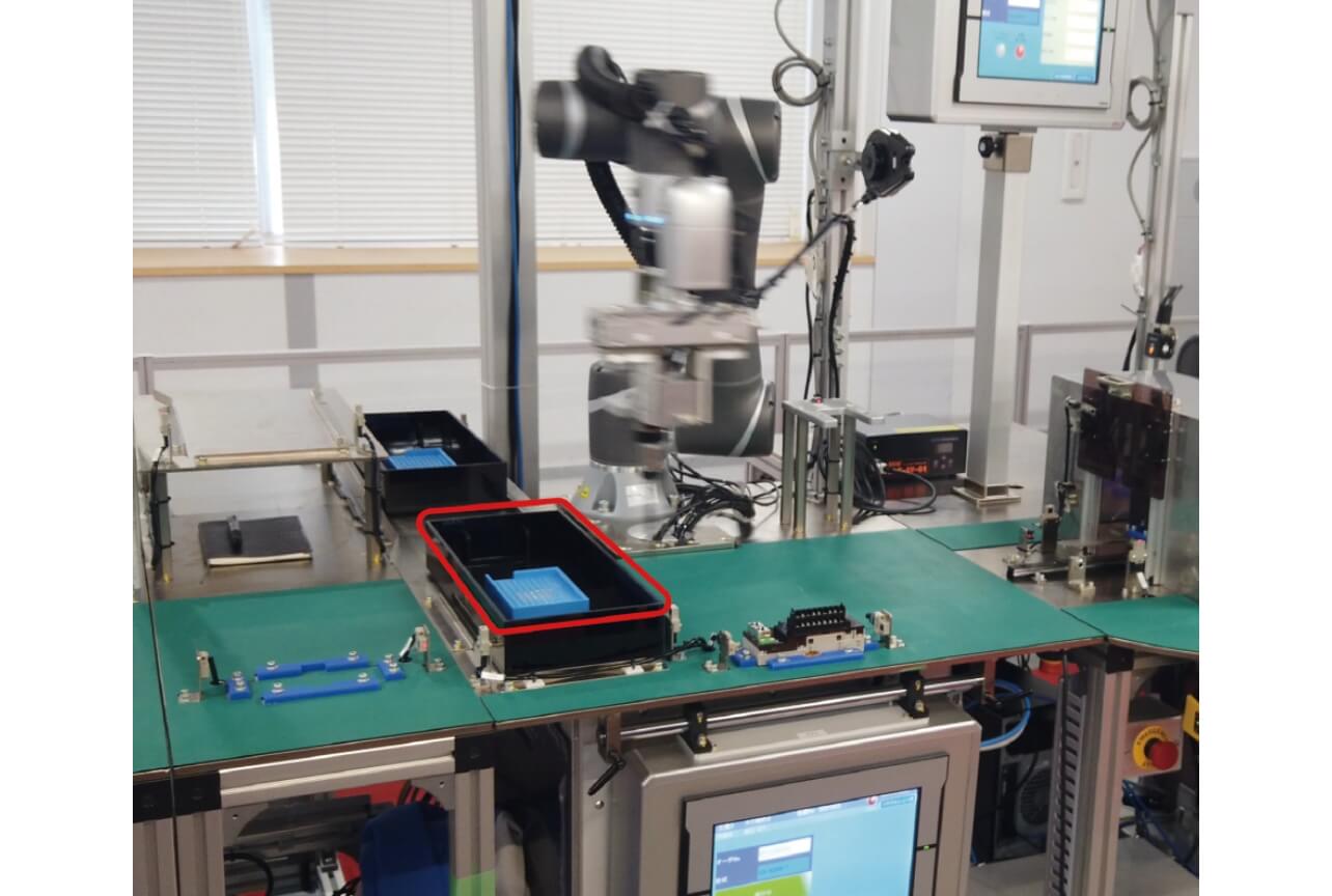
Similarly, each scenario considered for the operating space should be determined whether to be a scenario of misuse or not. Accident Scenarios Nos. 5 to 7, applicable to Behavior Categories a to c, respectively, should be determined as within the scope of reasonable foreseeability. Accident Scenario No. 8, applicable to Category-d, requires an analysis of the step and the motivation for the act of violation to determine whether the misuse is reasonably foreseeable. In the routine task, the cobot image-recognizes the screws in the pallet red-boxed in Fig. 5, picks up and transfers screws onto workpieces by vacuum suction, and performs screw fastening. Then, when the pallet has run out of screws, the cobot itself ejects the empty pallet and loads a new pallet. Therefore, pallet replacement falls outside the scope of the operator’s SOPs, saving the need for the operator’s involvement in the pallet replacement task. However, the operator might learn the cobot’s action timings in this operation step and attempt pallet replacement during the cobot’s screw-fastening operation time to reduce the manufacturing system’s operation time. Because this act can be determined as an attempt to improve productivity, Scenario No. 8 can be determined as one that assumes the misuse to be handled as a reasonably foreseeable misuse.
3.4 Points and effects of hazard identification and misuse analysis method application
Initially, we relied on the designer’s experience for hazard identification in the collaborative CLCS, as explained in Subsection 3.1. The method devised this time has enabled logical identification of hazardous events due to human misuse. We have also demonstrated that the method can determine the reasonable foreseeability of such misuses mechanistically without relying on designers’ design sense. As a result, for the accident scenarios assumed for the collaborative CLCS, we have clarified how much risk reduction is required.
Moreover, we have identified the following key points common to both accident scenario preparation based on the misuse classification in Fig. 3 and misuse analysis based on the flowchart in Fig. 4: causes/motivations of human actions, human entry points, and hazards involved/hazardous situations. With these points in our mind, we can identify hazards while minimizing the variability of experience and sense of risk assessment personnel, thereby moving ahead from quantity-over-quality hazard identification to systematic hazard identification to achieve improved design efficiency and reduced chances of overlooking risks. With these three focal points recorded using specific descriptions as in Table 3, we can explicitly show the composition of risks or the basis for judgment on the necessity of risk reduction measures to third parties other than personnel involved in risk assessment.
4. Conclusions
This paper presented the applicability of the existing safety standards and the perspectives of risk assessment as the criteria for identifying safety design problems in interactive manufacturing systems, described the methods devised to solve these problems, and showed the effect of these methods as applied to and tested on our collaborative CLCS.
Section 2 viewed interactive manufacturing systems from two perspectives of the workspaces and the human and machine task simultaneity and showed that these systems could be classified into two types: one for collaborative applications and the other for consecutive applications. As a result, for interactive manufacturing systems to which only the existing standards had been available to apply, a method was presented for developing an appropriate safety design matching the actual application. Section 3 presented systematic identification and description methods devised for accident scenarios due to human behaviors; their non-inclusion in the existing standards has so far prevented designers from logical safety design development. Section 3 also presented a method devised to determine the reasonable foreseeability of identified misuses. The application of these methods clarifies the judgment criteria for misuses to be considered at the design phase, allowing designers to fulfill their accountability to users for the safety of interactive manufacturing systems. The methods presented in this paper will serve well as guidelines for implementing logical, appropriate safety designs at optimum cost and with high user-friendliness.
Our future efforts will include delivering risk assessment sheet cases reflective of specific description methods for the key points in hazard identification mentioned in Subsection 3.4 and considering new risk reduction measures for interactive manufacturing systems that take into account reasonably foreseeable misuses. Through these efforts, we would like to contribute to the advancement of manufacturing systems with autonomous human-machine interaction, make proposals for new manufacturing systems with built-in safety, and have such proposals reflected in the existing standards and other regulatory documents.
References
- 1)
- Robots and Robotic Devices—Collaborative Robots, ISO/TS 15066, ISO/TS, 2016.
- 2)
- Robots and Robotic Devices—Safety Requirements for Industrial Robots— Part 2: Robot Systems and Integration, ISO 10218, ISO, 2011.
- 3)
- Safety of Machinery—General Principles for Design—Risk Assessment and Risk Reduction, ISO 12100, ISO, 2010.
- 4)
- Safety of Machinery—Risk Assessment—Part 2: Practical Guidance and Examples of Methods, ISO/TR 14121-2, ISO, 2012.
- 5)
- J. Reason, Menschliches Versagen: Psychologische Risikofaktoren und moderne Technologien, Heidelgerg, Spektrum Akademischer Verlag (in German), 1994.
- 6)
- A. Neudörfer, Konstruieren sicherheitsgerechter Produkte, K. Tanaka, Trans. and Ed., 1st ed. (Japanese translated version), Japan: NPO Safety Engineering Laboratory (in Japanese), 2002, 365p.
The names of products in the text may be trademarks of each company.