


Introduction of System Safety Analysis Method (STAMP/STPA) in the Development of the PCB Inspection System
- STAMP
- STPA
- Factory Automation
- Software Engineering
- Hazard Analysis
Traditionally, system behaviors has been expressed by creating activity and sequence diagrams in the system design of the PCB Inspection System. However, it is difficult to specify the abnormal behaviors of the systems in the design phase to prevent the inclusion of defects as the system becomes highly functional and complicated.
The authors have tried to apply STAMP/STPA, which is one of the methods of system safety analysis in the development of the PCB Inspection System. As a result, it has been able to acquire the cause of failures that would have been difficult to extract with existing system design methods, and it helps to maintain the high reliability of the system even if it becomes more sophisticated and complex in the future.
This paper describes an analysis case applied to STAMP/STPA for the development of the PCB Inspection System and proposes a method for improving the efficiency of the analysis work obtained through this approach.
1. Introduction
In surface-mount technology (SMT), higher-density packaging and finer miniaturization of devices have been underway, driven by the recent development of advanced driver-assistance systems (ADAS) and 5G-led communications technologies supporting the development of automated driving technology. High reliability and stability are required of SMT to build product safety into electronic equipment supporting the social infrastructure. The final process in SMT assembly relies heavily on PCB inspection systems that inspect whether devices are correctly mounted and soldered to the boards.
In recent years, PCB inspection systems have been required to grow and expand in functionality. With heavy traffic in system-host and inter-application communications being unavoidable in delivering diverse functions, system configurations are becoming increasingly more complicated. Besides, image data are increasing their importance for big data and AI purposes. Hence, PCB inspection systems are required to have high enough reliability for continuous stable operation even in environments where large amounts of large-size image data are very frequently sent and received or read and written via an internal factory network.
Traditionally, activity diagrams and sequence diagrams have served system designers’ needs to express system behaviors. However, these diagrams can only express general normal system behaviors and typical abnormal system behaviors. Abnormal system behaviors are difficult to identify with pinpoint precision in the design phase to prevent the inclusion of defects. As a result, defects have occurred, causing problems irreproducible in in-house test environments to surface under certain customer environments.
The present author and colleagues pursued applying STAMP/STPA, a new method of safety analysis based on system thinking as a design analysis method for OMRON to strike a balance between the high functionality and high reliability required of its PCB inspection systems for its aim of building a zero defect production line. STAMP/STPA is said to allow discernment and elimination or reduction of “unknown unknowns,” formerly detectable only during operation, including even those in complicated systems in the early stage of the development processes1).
This paper presents an analysis of STAMP/STPA application to PCB inspection system development and proposes a method of analysis work efficiency improvement as an outcome of the present author’s project.
2. STAMP/STPA
2.1 What is STAMP/STPA?
Systems-Theoretic Accident Mode and Processes/Systems-Theoretic Process Analysis (STAMP/STPA) is an analysis method proposed by Professor Nancy G. Leveson of the Massachusetts Institute of Technology for problems caused by interactions between system components1-2). Its application has gone beyond the aerospace field3) and spread into social infrastructure areas4).
Conventional analysis methods, such as fault tree analysis (FTA) or failure mode and effect analysis (FMEA), have been available since the 1960s as methods of analyzing single failures in equipment or organizations. These analysis methods, however, have limits for application to complicated modern systems under continuous progress. The reason is that accidents will occur in complicated systems due to faulty single components and inter-component communication mismatches. The STAMP/STPA method proposed by Prof. Nancy G. Leveson is a top-down process and has its basis in the concept of taking bird’s-eye views of interactions caused directly or indirectly by intra-system components to control accidental emergent properties and prevent accidents.
2.2 STAMP/STPA analysis procedure
The procedure for STAMP/STPA analysis goes as follows:
Step 0: (Preparation 1) Discern accidents, hazards, and safety constraints.
Define the accidents and hazards to be analyzed in a system. Accidents are defined in a broad sense as unacceptable losses of some values for interested parties. Hazards refer to a state that is only one step removed from an accident and should not be left unsolved. Then, finally, discern system safety constraints for hazard control.
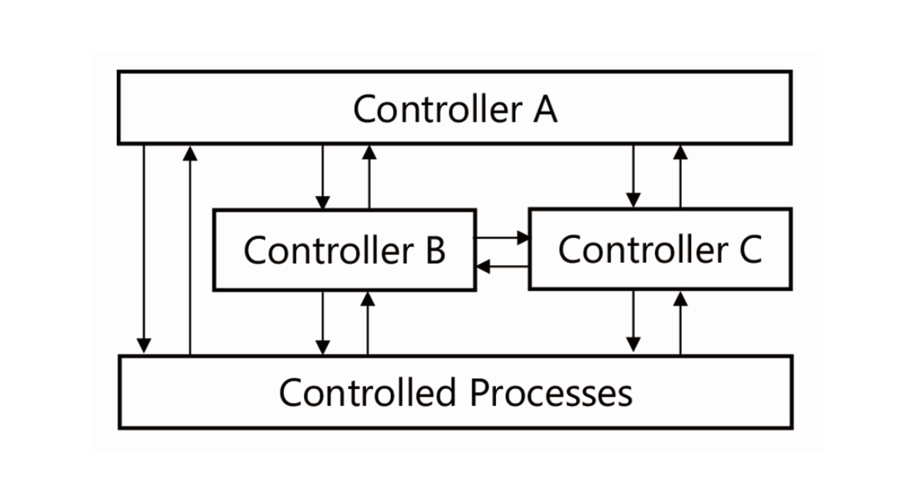
Step 0: (Preparation 2) Build the control structure.
Build a control structure by analyzing, together with inter-component interactions, the system’s components (subsystems, equipment, organizations, etc.) likely to lead to the establishment of safety constraints. Fig. 1 shows a typical control structure:
Step 1: Identify unsafe control actions (UCAs).
Discern controller-issued inter-component instructions (control actions) necessary to activate safety constraints. Then, identify unsafe control actions (UCAs) from the instructions thus discerned. Four guidewords are available as clues to help identify UCAs.
- Not providing causes hazard.
Non-provision of any control action required for safety leads to a hazard. - Providing causes hazard.
An unsafe control action is provided that leads to a hazard. - Too early/too late, wrong order causes hazard.
A probably safe control action provided too late, too early, or out of sequence leads to a hazard. - Stopping too soon/applying too long causes hazard.
A safe control action stopped too soon or applied too long leads to a hazard.
Step 2: Identify hazard causal factors (HCFs).
For each UCA identified in Step 1, discern the relevant controllers and control target processes and create a control loop diagram by referring to an abstract model of cause-and-effect scenario generation to identify hazard causal factors (HCFs).
A control loop diagram selectively shows only components relevant to the UCAs of interest. Its intended use is to focus consideration on two components rather than to consider multiple inter-component interactions simultaneously. An abstract model of cause-and-effect scenario generation is a model used to help identify HCFs. It contains a list of common causes of the occurrence of HCFs.
3. Introduction into PCB inspection system development
3.1 Preliminary preparation
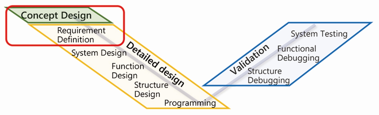
The present author’s project took place as the red-boxed part from the conceptual design phase to immediately before the system design phase of the Inspection System Division’s development process shown in Fig. 2:
As the preliminary preparation for analysis, a schematic diagram of the whole system shown in Fig. 3 was prepared to allow the analysts to ensure a shared understanding about the system. The rest of this section explains the roles of the system components.
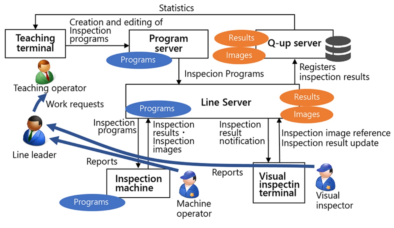
- Teaching terminal: It creates and edits inspection programs necessary for board inspections.
- Program server: It stores inspection programs.
- Line servers: They are installed for every several production lines to double as a replica server for inspection programs and as the primary storage of inspection results and inspection result images.
- Q-Up server5): It is installed with a database system to perform analysis of inspection results.
- Inspection machine: It determines the pass/fail of boards.
- Visual inspection terminal: Boards rejected by the inspection machine as defective products are visually inspected by visual inspection personnel for the final pass/fail judgment.
3.2 Step 0 (Preparation 1): Discern accidents, hazards, and safety constraints.
System-related accidents, hazards, and safety constraints were defined as follows:
Accidents:
- Production line stoppages due to OMRON-provided inspection system application software.
Hazards:
- A situation where the inspection machine takes much time to start, causing the inability to start an inspection
- A situation where the inspection machine refuses to load an inspection program, causing the inability to switch the model to be inspected
- A situation where a board to be visually inspected is held off from undergoing a visual inspection although the board is already inside the visual inspection terminal
- A situation where the inspection machine stops when detecting an anomaly due to an inspection program mismatched in content
- A situation where a board, having reached the inlet of the inspection machine emptied of boards, is refused to go inside
- A situation where a board done with inspection remains inside the inspection machine although the downstream machine is ready to take the board in
Safety constraints (reversals of hazards):
- Inspection readiness must be reached by the time of production start.
- The inspection machine must be able to load an inspection program normally and be ready for setup.
- The visual inspection must be ready to start when the board reaches the visual inspection terminal.
- The inspection machine must not hang up due to a mismatch with an inspection program.
- When a board reaches the inspection machine emptied of boards, the board must go inside the machine and undergo inspection.
- When a board is done with the inspection and the downstream machine is ready to take it in, the board must be taken out from the inspection machine immediately.
3.3 Step 0 (Preparation 2): Build the control structure.
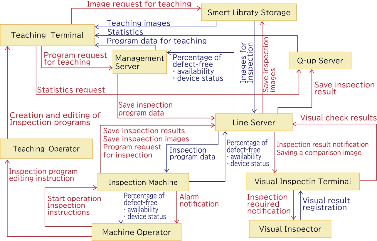
Fig. 4 shows the control structure built through this step. As shown in this figure, STAMP/STPA has as one of its advantages its applicability from the conceptual design phase for determining the approximate components of the system. The control structure in Fig. 4 shows some differences in system components from the schematic diagram shown in Fig. 3. These differences mean that changes occurred during the design process.
3.4 Step 1: Identify unsafe control actions (UCAs).
A total of 51 UCAs were identified. Some of the identified UCAs are shown below as examples (Table 1):
| CA | Inspection program request |
|---|---|
| From | Inspection machine |
| To | Line server |
| Not providing causes hazard. | • Although an inspection program must be obtained, no request is made for one necessary for the setup. |
| Providing causes hazard. | • A request is made for a wrong inspection program. • Inspection program saving fails. |
| Too early/too late, wrong order causes hazards. | • The line server gets overloaded and unable to handle processing for other inspection
machines. • Because of the delayed start of the request for an inspection program, no inspection program is available at the start of production. |
| Stopping too soon/applying too long causes hazards. | • An inspection program takes too long to save and fails to serve for production. |
For UCA identification, it is vital to include the context (situation) as background information. For any situation encountered that does not translate easily into a UCA description, including the context, the author made efforts to use wording that goes something like “something/someone is/does such-and-such despite/although....” A typical description of this sort would go something like “Although the inspection result output must be completed by the time the next board to be inspected arrives, it has not been completed yet” when, for instance, a UCA “inspection result output is delayed” occurs.
3.5 Step 2: Identify hazard causal factors (HCFs)
The present author’s project identified a total of 85 HCFs. Some of the identified HCFs are shown below as examples (Table 2):
| HCF | HCF scenario |
|---|---|
| Discrepancies between a management file and an entity file | Although new programs are already on the server, the inspection machine fails to recognize the new revision data. |
| Management server mutual exclusion error | When inspection programs update occurs in multiple teaching terminals simultaneously, the inspection program or its management information fails to be saved correctly. |
| Overloaded line server | The line server gets overloaded and unable or slow to respond to requests from the inspection machine for inspection programs. |
| Unauthorized retry processing | Inspection program saving failure causes repeated request processing. |
For HCF identification, the present author kept in his mind the following point to simplify problem handling:
A Japanese proverb states that when the wind blows, the barrel maker gets rich. This proverb provides an example of a figure of speech for effects extending to seemingly completely unrelated places or things and suggests that if pushed too deep, an inquiry into a causal relationship would end up concluding that everything could be the cause of a problem. To simplify problem handling, the present author avoided delving deeper than primary causal relationships. In the case of, for example, the proverb “When the wind blows, the barrel maker gets rich,” the line not to be crossed would be drawn at the following: “When dust is raised by a gust of wind and gets into people’s eyes, the blind population increases as a result.” If this scenario is reworded according to the descriptive convention for HCFs, the problem will be “A gust of wind raises a cloud of dust,” and the countermeasure would be “On a windy day, water should be thrown onto the ground to prevent raised dust.”
As shown in Fig. 4, the PCB inspection system consists of multiple components connected via a network. The STAMP/STPA procedure places the focus on inter-component instructions to identify problems arising from inter-component interactions. As a result, similar HCFs were overlapped and identified among multiple hosts. Hence, the present author chose to consolidate each group of similar HCFs into a consolidated HCF and consider countermeasures against each consolidated HCF, rather than consider and plan countermeasures against individual HCFs. This choice allowed the present author to reveal the variability among HCFs and the existence of HCFs overlooked during identification and produced the effect of making countermeasure consideration easier. Some examples of the consolidated HCFs are shown below, together with those of HCF identification scenarios (Table 3):
| Consolidated HCF | HCF scenario |
|---|---|
| The server gets overloaded and fails to accept/return data. | • Multiple teaching terminals simultaneously start an inspection program update task,
resulting in multiple concurrent requests for inspection program saving. • Consecutive inspection program saving operations cause high disk loads. • Inspection program saving failure causes repeated request processing. • The machine connected to the line server saves multiple large-size inspection images simultaneously. |
| A conflict occurs between the management information and the entity. | • Although a new program is already on the server, the inspection machine requests
old revision data immediately before an update of management information. • While the inspection program entity file is in the middle of saving, only the management file is updated (or vice versa). When an attempt to use the inspection program (or the management file) is made at this time, the two files conflict with each other. • An image that supposedly exists according to the management information is not found on the storage. |
| Saving of a corrupted/inconsistent data file; Data | • A file saving operation is canceled halfway through, resulting in garbage data left
behind. • An exception occurs during a saving process, resulting in half-done data left behind. • As a result of a network disconnection occurring at the final step of a process consisting of multiple transactions, the results of the transaction executed at the beginning are not cleared. |
3.6 Planning countermeasures against HCFs
The scope of the procedure defined for STAMP/STPA extended up to the end of HCF identification. Nevertheless, measures were considered for excluding the HCFs identified during the PCB inspection system development process and were fed back to the system specifications or the functional specifications for each application.
4. Discussions
Some of the UCAs newly identified through the application of the STAMP/STPA process had the following contents (Table 4):
| CA | Inspection program saving |
|---|---|
| From | Management server |
| To | Line server |
| Too early/too late, wrong order causes hazards. | Before the program body has been fully circulated in the entire inspection machine after consecutive executions of inspection program update tasks, the management data are updated, resulting in compromised data integrity. |
| CA | Inspection result saving |
|---|---|
| From | Line server |
| To | Q-Up server |
| Stopping too soon/applying too long causes hazards. | While inspection results take much time to be saved to the Q-Up server, the line server remains in a wait state. In the meantime, no inspection results from the inspection machine can be saved. |
Using the control structure as the basis for consideration, the present author obtained a bird’s-eye view of the whole system and found structural shortcomings in light of the original objective.
The present author successfully identified the risks of apparently common defects that show behaviors difficult to express in activity diagrams or sequence diagrams and may cause a problem, depending on the timing of processing. From the QCD perspective, any development project would benefit from implementing fundamental measures against these risks while keeping track of problems from the initial stage of the development process and sharing information on the problems via obtained tables and figures among development team members throughout the analysis process. No comparable benefit would be available from addressing the risks individually after detecting actual problems in the testing phase near the end of the development process or in the customer environment.
STAMP/STPA demands considerable analysis workload for its introduction because Step 2, “Identify HCFs,” has to be repeated for each of the UCAs identified at Step 1, “Identify UCAs.” For widespread use of this approach, the present author considers it necessary to improve the efficiency of the analysis work involved while maintaining the STAMP/STPA’s ability to control emergent properties. In the present author’s project, the consideration and planning phase efficiency was improved by consolidating individually identified HCFs while considering countermeasures against HCFs. A method of further efficiency enhancement would be provided by proceeding with the procedure up to Step 1, “Identify UCAs,” then consolidating UCAs encountered in similar contexts, and considering HCFs for the consolidated UCAs. Such a method would allow consolidated consideration of HCFs caused by host-to-host network connections, and hence would be particularly useful for distributed systems, such as PCB inspection systems.
5. Conclusions
Aiming to realize high-quality system development for the functional expansion and enhancement requirements expected to be imposed in the future, the present author and colleagues performed safety analysis based on STAMP/STPA by applying STAMP/STPA to a PCB inspection system design and defining accidents as production line stoppages due to OMRON-provided inspection system application software.
Taking a bird’s-eye view of the whole system in the form of a control structure diagram and checking against guidewords to identify problems likely to occur because of inter-component instructions, the present author and colleagues successfully identified risk items to abnormal system behaviors unidentifiable with activity diagrams or sequence diagrams only.
The STAMP/STPA analysis process presented above enabled the visual representation of the whole system, allowing the recording of the traceability of problems, their preceding contexts, and countermeasures against them, thereby contributing to domain knowledge formalization. Simultaneously, the author obtained promising results that predict that OMRON’s system products would remain reliable even if they became more complicated and functionally enhanced.
On the other hand, the analysis work involved will require perseverance and effort. The present author considers it indispensable to improve analysis work efficiency to lower the barriers to applying STAMP/STPA to development projects and increase opportunities for active use. In the present author’s project, individually identified HCFs were consolidated to allow efficient consideration of countermeasures. Besides, the present author proposed to improve the efficiency of HCF identification through the consolidation of UCAs similar in context.
The present author and colleagues will use this STAMP/STPA approach to contribute to system products’ improved reliability and will strive to accumulate the knowledge of points creatively worked on during analysis and vital points specific to PCB inspection systems to improve the applicability of STAMP/STPA to the designs.
References
- 1)
- N. G. Leveson and J. P. Thomas, STPA Handbook (Japanese translated version), http://psas.scripts.mit.edu/home/get_file2.php?name=STPA_handbook_japanese.pdf (accessed Aug. 4, 2020).
- 2)
- Information-Technology Promotion Agency, Introduction to STAMP/STPA ~ New Safety Analysis Method based on System Thinking (in Japanese), https://www.ipa.go.jp/files/000051829.pdf (accessed Aug. 4, 2020).
- 3)
- R. Ujiie, “A Typical Application of STAMP/STPA to JAXA H-II Transfer Vehicle (HTV) Project,” (in Japanese), J. Soc. Inst. Control Eng., vol.55, no.5, pp.405-409, 2016.
- 4)
- S. Kitamura, “JR East’s Efforts for the Effective Use of STAMP,” (in Japanese), SEC J., vol.13, no.4, pp.30-37, 2018.
- 5)
- OMRON Corporation, “Productivity Improvement Support Software Q-up System ‘Starting from Quality’,” (in Japanese), https://www.fa.omron.co.jp/data_pdf/cat/q-upnavi_scwb-046a-1.pdf?id=1463, (accessed Oct. 20, 2020).
The names of products in the text may be trademarks of each company.