


Safety Light Curtain System That Improves Preventive Maintenance Effects by Realizing Information-Driven Production Sites
- Information driven system
- Safety light curtain
- IO-Link
The environment for constructing information systems, such as faster networks, lower costs, and larger storage capacity, is becoming available at the production site. With these technologies, OMRON realizes an information system that covers the sensor level using the open network IO-Link as a future factory. And the IO-Link compatible safety light curtain (active opt-electronic protective devices) system has been released to support the realization of this future factory concept. In existing products, a dedicated tool is required, although useful maintenance information can be provided, and it is difficult to link to other devices in a large-scale system. This problem is solved by designing the system configuration and communication control by maintaining the existing function. As a result, we have achieved products that are high-performance, small, and low in cost. We can make it easier to deliver the value of information-driven system to customers. By expanding this method to other safety components in the future, it is possible to contribute to the improvement of the customer’s production equipment operating rate through the realization of the above future factory concept.
1. Introduction
Some time has passed since market needs became apparent for collecting diverse information via a network from the input, logic, and output components constituting production systems on manufacturing shop floors to utilize the resulting data for preventive maintenance. In response to such market needs, many products have been developed so far by individual manufacturers in the FA industry, including OMRON. Up until now, however, many cases of development efforts have extended primarily to logic-type components, more specifically, PLC remote I/O units. As a result, informatized preventive maintenance has produced only a limited effect. One of the factors behind the scene was the low coverage of information due to the difficulty in networking input-type components, which account for the largest proportion of production system constituents. For more effective implementation of preventive maintenance, all components that undergo preventive maintenance must be made network compatible. Therefore, customers have made it an important selection criterion for input components whether they can be informatized at a lower cost while remaining small in size. The reason is that input components are large in quantity and variety and easily affected by the line cost or the impact during installation.
On the other hand, when made network compatible, these components ended up with an increase in size or cost because of the inclusion of dedicated circuits. Consequently, input components have lagged in informatization, thereby leading to a failure in expanding the range of network-compatible models. Besides, evident needs for informatization were not so high among customers as now. The added value available from the preventive maintenance informatized only to a limited degree in such underdeveloped environments was regarded as unsatisfactory to justify the adoption of network-compatible input components as compared with the cost of the components per se or the additional costs, including those of design person-hours for system construction.
In recent years, however, dedicated electronic parts for networking have decreased in price and size. Besides, the range of network-compatible models has also expanded. Moreover, besides higher-speed networks as information gathering channels, larger-capacity, lower-priced data storage cloud and database services have become available along with the announcement and commercialization of devices and technologies for informatized systems, including AI developed to analyze and effectively use stored data. Thus, development is underway of environments convenient for meeting the market needs that have been known for some time.
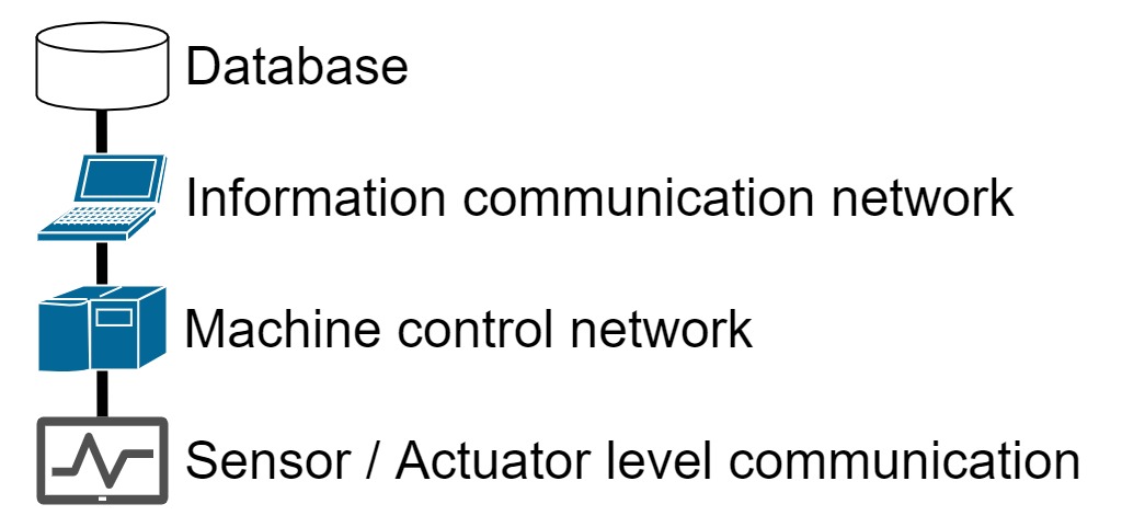
OMRON also aims at realizing future factories where humans and machines can exactly understand each other. With IoT connecting all things on a manufacturing shop floor to one another and humans, it will be possible, for example, to detect signs of equipment failures so that the equipment can respond autonomously and identify the causes of product defects1). On many manufacturing shop floors, IoT-ization is underway of the machine control layer (Fig. 1) and the layers thereabove through EtherNet/IP, EtherCAT, or other protocols. Under this concept, OMRON has developed a lineup of IO-Link-compatible devices, the constituents of the sensor-level open network below these upper layers, ahead of all others, and has begun to promote the construction of informatized systems down to the sensor level. The safety light curtain (Model F3SG-SR/PG series) presented herein and its accessory, an intelligent tap (Model F39-SGIT-IL3), are the first of its kind compatible with sensor-level informatization among OMRONʼs safety components. As a result, information can now be aggregated from general-purpose components as well as safety components. This ability expands the coverage of informatization and increases the amounts of information deliverable to customers.
The safety light curtain of interest herein is a photoelectric sensor system with multiple optical axes. This sensor system is mainly used to detect entries of persons from safety areas into danger areas. A production system is built to turn on the output of the safety light curtain so that any mechanical equipment in the danger area, such as a machine tool or a press machine, can operate only when the incident light is detected along each optical axis. In other words, when a passing person blocks any of its optical axes, the safety light curtain is powered off, as a result of which the equipment stops, thereby preventing accidental personal injuries. Conversely, the equipment cannot operate with the safety light curtain output turned off. Assume, for instance, that a beam of light incident on one of the light-receiving parts is erroneously determined as blocked because of products with dirty surfaces. Then, even with no one about to enter the danger zone, the equipment would stop running, resulting in an unnecessary decrease in the customerʼs production systemʼs operating rate. Assume that a mechanism is available that can continuously monitor the amount of light received along the optical axes in such a situation. Then, the detection of a gradual decrease in the amount of received light will become possible, whereby the operating rate of the customerʼs production equipment can be maintained through a maintenance action, such as cleaning, before any interruption of the safety light curtain.
2. System configuration
2.1 Overall configuration
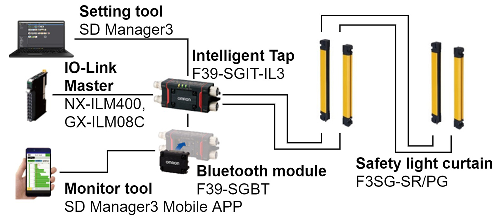
The minimum unit for a safety light curtain system is a set that consists of a light emitter paired with a light receiver. As shown in Fig. 2, two sets can be connected into a single-set safety light curtain system with an increased number of optical axes. Where the safety light curtain system is used for informatization purposes in the sense of this paper, information from a safety light curtain (Model F3SG-SR/PG) will be converted via an intelligent tap (Model F39-SGIT-IL3), an accessory to the Model F3SG-SR/PG, into the format supported by the IO-Link protocol. The system thus configured can then be interfaced with the Sysmac3) Integrated Platform via an IO-Link master (Model NX-ILM400 or Model GX-ILM08C). Note that the information notification function for PCs or mobile devices has been available through the SD Manager-series dedicated safety light curtain configuration tool since the release of the existing safety light curtain series and has been upgraded this time for combined use with IO-Link-compatible devices.
2.2 Intelligent tap
The critical component for implementing an informatized system is an intelligent tap, which serves as a gateway compatible with multiple communication protocols. In this system configuration, the gateway function is provided by an independent component separate from the safety light curtain. This configuration allows us to provide a no-frills safety component in optimum condition to customers who need only the function of the same conventional safety component as before or to provide a system implemented with the addition of an intelligent tap to customers who seek the added value of informatization besides the conventional function.
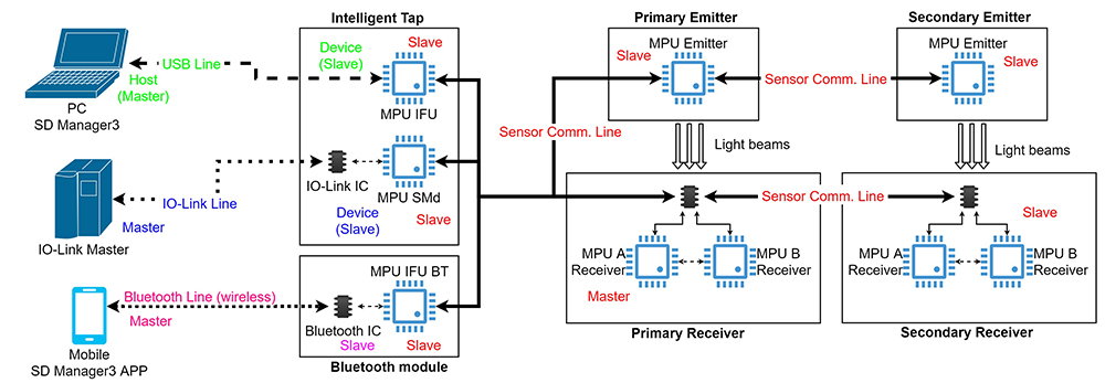
Fig. 3 shows a configuration diagram based on the configuration described above and mainly focused on the communication protocols and the associated master-slave relations.
*Open in New Window
3. Technical challenges
3.1 Smaller size and lower cost
Safety light curtains provide personal safety, which was formerly deemed as a special added value to production. Nevertheless, with the recent market well aware of the importance of safety implementation, safety assurance measures using a safety light curtain have come to constitute a commonplace part of production equipment design requirements. As a result, it has become essential for safety light curtains to meet the needs for smaller sizes and lower costs similarly to general-purpose components. When size requirements assume attachment to aluminum profiles in a market where safety component informatization is generally relatively low in demand, an intelligent tap first and foremost must fall within a price range reasonable to customers while meeting the mandatory requirements of small size and low cost, which are similar to safety light curtains.
In addition, similar to safety light curtains, the intelligent tap is required to have an architecture as a safety component. Such an architecture has a tradeoff relationship with size and cost reductions. More specifically, such an architecture needs an internal configuration with added fail-safe circuit redundancy to meet the required safety level. Moreover, the intelligent tap, an off-board device, must meet demanding environmental resistance requirements, including sealing performance, and must further meet multiple sets of insulation requirements for establishing connection from multiple communication masters in separate systems. The technical considerations we made revealed that the intelligent tap was considerably off the size and cost requirements. Thus, fundamental corrective measures had to be implemented.
3.2 Software for implementing multiple functions
Besides the basic power-off function used when no incident light is detected along any of its optical axes, a safety light curtain features a wide variety of functions provided mainly by its software. Meanwhile, an intelligent tap is required to have DIP and tactile switches as quick setting and external I/O interfaces with customersʼ safety light curtains, in addition to internal communication buses for informatization and a multiprotocol gateway function compatible with the IO-Link, USB, and Bluetooth communication devices. For compatibility with the requirements presented in the previous section, these many functions and their performance must be provided by an inexpensive MPU and its peripheral circuits.
This point is described in the present paper, focusing on the communications perspective, particularly contributory to implementing the informatized functions. As shown in Fig. 3, the master-slave communications in Table 1 coexist in the system. What is required is to support them at the same time. More specifically,
- 1) information notification control from a master/primary light receiver to each slave; and
- 2) compatibility between the slave functions of the SMd (see Table 1), each using a different protocol (sensor-to-sensor and IO-Link communication protocols).
| Protocol | Master/host | Slave/device |
|---|---|---|
| Sensor-to-sensor communication (proprietary bus) |
Primary light receiver | Secondary light receiver (coupled
light receiver)
All light emitters Smart module (SMd) (*1) Interface unit (IFU) (*1) Interface unit Bluetooth module (IFU BT) |
| IO-Link communication | IO-Link master | SMd |
| USB communication | PC | IFU (*2) |
| Bluetooth communication |
Mobile device | IFU BT (*2) |
(*1) The names of the internal functions of the intelligent tap. SMd is used to run all the controls of the intelligent tap in addition to communication. The IFU and the IFU BT are used exclusively for their respective protocol-compliant communication.
(*2) Exclusive to each other. These two modes of communication do not co-occur.
Some competitorsʼ products also have accessories that provide a gateway function but support only one protocol. Unlike our intelligent tap, none are known to constitute a component that singly supports three different protocols (USB, Bluetooth, and IO-Link). Moreover, our intelligent tap is novel in that it can use the IO-Link protocol simultaneously with either the USB protocol or the Bluetooth protocol. We decided not to limit our intelligent tap only to the IO-Link protocol for two reasons. One is to use different protocols, depending on the type of information. When in the normal state, the intelligent tap collects simplified information for continuous monitoring to be notified via the IO-Link channel to the general-purpose network to perform preventive maintenance. When an anomaly occurs, such as a problem condition, the intelligent tap uses dedicated tools and detailed information to perform efficient troubleshooting via the USB/Bluetooth channel. This network optimization has led to a reduced system cost. The other is to consider existing customers who use a dedicated tool connected directly to a stand-alone safety light curtain with no network in between. The use of the IO-Link protocol requires the installation of many peripheral devices, such as PLCs. Hence, for customers satisfied with using a safety light curtain monitored by a conventional dedicated tool, such a change means extra development costs due to the installation of new hardware, such as PLCs, or a change in system configuration. We feared that any change in the operating method of a system might force the operator to change the operating procedures at the expense of customer convenience.
The existing OMRON-built safety light curtains support only either USB or Bluetooth communication via an IFU/IFU BT-equivalent device (see Table 1). The aim here is to expand the range of supported protocols as explained above and implement the new function of their simultaneous use. We will then be enabled to provide our customers with additional effective means of informatization and their options.
The primary light receiver to be used as the communication master for the above sensor-to-sensor communication protocol is required to provide the following modes of information notification and exchange as well as their corresponding response performance:
-
1) Communication with the SMd
– External input information to the intelligent tap (*1)
– Internal data for sensor control
– Data request check (*2)
– Transmission of data for external devices
(Data for IO-Link master) (*a) -
2) Communication with the IFU and the IFU BT
– Data request check (*2)
– Transmission of data for external devices (data for PCs/mobile devices) (*a) -
3) Communication with the secondary light receiver and light emitter/sensor
– Instructions for transmission of data for external devices (*b)
– Internal data for control purposes (Control flag and internal status) (*3)
| (*1) | Not shown in any of the figures herein. |
| (*2) | The sensorʼs external devices (SMd, IFU, and IFU BT) check for any information request from individual communication masters. Then, the primary light receiver recognizes data transmission requests from each external communication master. In this way, the primary light receiver transmits information (*a) while the other light receivers or light emitters send information at instructions (*b) to external devices, respectively. |
| (*3) | Intended for implementing the light emission and reception functions or diagnostic functions and mainly used for synchronization control. |
4. Measures for system implementation
4.1 Size and cost reduction
The intelligent tap considerably off the required specifications underwent a review of its architecture for safety implementation. An attempt to meet the applicable requirements of the International Safety Standards using the standard methods specified therein requires a redundant configuration for the DIP switches used as operation-setting interfaces with the safety light curtain or for the MPU for product operation control. This configuration, however, would reduce the available mounting area and push up the required cost, resulting in failure to meet the required product specifications. Hence, the architecture and software logic were developed to meet the safety requirements with the safety light curtain and the MPU remaining a single system, respectively. Through system implementation on a single-system basis, we reduced the mounting area for the parts per se and their peripheral circuits by 10 percent and the implementation cost for the portions at issue by 30 percent without compromising the customer-friendly configurability. The system thus configured was combined with a newly developed logic, whereby the probability of dangerous failure per unit time for determining the achieved safety level was successfully reduced to approximately a 100th of its original level. As a result, the above probability of dangerous failure has become equivalent to that achievable with redundant system architecture. Our product received approval from a third-party notified body and achieved the highest safety level for FA equipment and safety light curtains compliant with the applicable International Safety Standards. While one of the safety criteria for safety light curtains is the probability of a dangerous failure per 30 years, the frequency of this productʼs dangerous failure has been reduced down to once every 200 years4-6). Meanwhile, our intelligent tap has been implemented with a body volume less than a half of that of the IO-Link-compatible accessories to our competitorsʼ safety light curtains and further with additional functions, including operation-setting input interfaces and the support of protocols other than the IO-Link protocol.
4.2 Intra-system information control by the primary light receiver
4.2.1 Overall concept
When viewed with a focus on communication handling, each light receiver and light emitter perform a one-way information notification process and a two-way information exchange process during a single cycle. The SMd, IFU, and IFU BT, which are built-in devices of the intelligent tap but are external devices as viewed from the light receiver and the light emitter, perform continuous reception processing, as illustrated in Fig. 4.
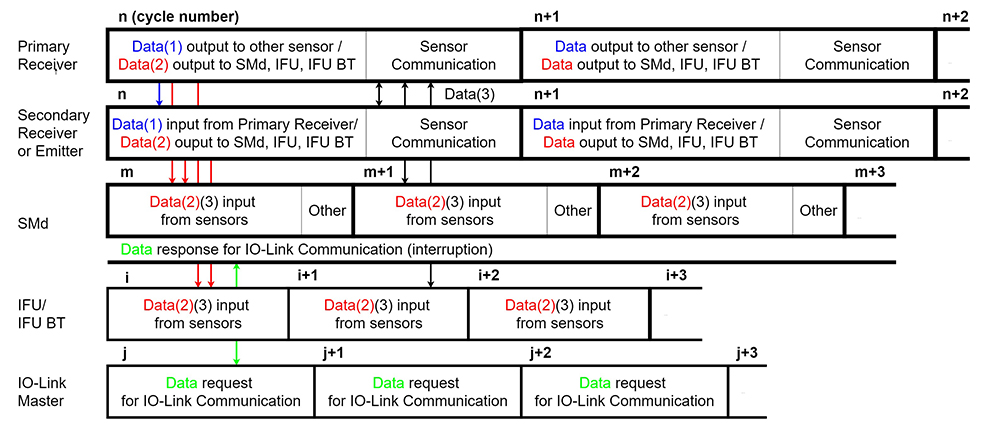
A safety light curtain requires high-precision time synchronization on the order of μ-seconds between light receivers and light emitters as well as between interconnected light receivers or light emitters to perform fast, accurate light emission and reception processes with multiple optical axes. The information exchange and timing control required to control these processes are performed in sensor-to-sensor communication (“Sensor Communication”), as shown in Fig. 4.
In the other information notification processes, information notifications from the light receivers and the light emitter to individual communication masters occur upon request from a communication master, such as an IO-Link master, a PC, or a mobile device, besides internal processing, such as sensor display processing. Note, however, that a mechanism is required to notify different information separately to, for example, both the IO-Link master and a PC even in the event of simultaneous occurrence of an error log information request from the IO-Link master and a received light amount information request from the PC.
4.2.2 Communication establishment method in the primary light receiver
To serve its intended purpose, our system must have the ability to perform communication tasks conflict-free at a frequency sufficient to meet all the communication requirements presented above and the performance requirements for individual communications. The communication tasks to be performed are divided as follows:
- 1) One-way communication for notifying information from each light emitter and light receiver to the SMd or the IFU/IFU BT (“Data (1) and (2)” in Fig. 4); or
- 2) Two-way communication for infra-system information exchanging between the primary light receiver/master and each slave (“Data (3)” in Fig. 4).
The mechanism for performing these tasks consists of a light emitter and a light receiver performing a data output task (“Data output to XX”) during the first half of a cycle and a sensor-to-sensor communication task (“Sensor communication”) during the second half of the same cycle as shown in Fig. 4. During sensor-to-sensor communication, the primary light receiver collects information “Data (3)” from the devices connected to the system and responds to requests from the external communication masters during the data output time interval by issuing instructions as to which data should be transmitted from which light receiver or which light emitter to which communication master. Based on these instructions, the output of information “Data (2)” occurs during the one-way communication for the subsequent cycle.
Our system adopts a communication command table-based method of consecutive sequential execution for each control cycle as a specific method of performing sensor-to-sensor communication. Fig. 3 shows an example of a possible configuration of Model F3SG-SR/PG: alternative configurations are also allowed in which, for instance: three sensors are connected to one another or paired light receivers, or light emitters are not electrically connected to one another. The required communication may differ depending on the system configuration. Hence, the safety light curtain system automatically recognizes the as-of configuration at start-up, selects an optimum communication command table for the configuration based on the required counterpart or frequency of communication, and executes communication commands during normal processing to perform its intended functions.
During the execution process, our system must be able to recognize information requests from external devices and consider an optimally ordered sequence of commands in the communication table to allocate an appropriate amount of data output time to individual requests, even if requested for different information by multiple different communication masters. The system presented herein assumes two-pattern simultaneous handling for information requests from outside because information requests come in from either the IFU/IFU BT or the SMd. Note that three-pattern simultaneous handling is not considered for this system because the IFU and the IFU BT are exclusive to each other, as footnoted below Table 1. Table 2 shows an example of a specific communication command table. This example of a communication table contains 10 elements.
| No. | Process | Recipient |
|---|---|---|
| 1 | External information request check | IFU |
| 2 | External information request check | IFU BT |
| 3 | Internal status exchange | Secondary light receiver |
| ・ ・ ・ |
・ ・ ・ |
・ ・ ・ |
| 6 | External information request check | SMd |
| 7 | Internal status exchange | Primary light emitter |
| ・ ・ ・ |
・ ・ ・ |
・ ・ ・ |
| 10 | Internal status exchange | SMd |
As shown in this example, to keep the compatibility between information exchange and information notification, the communication command table is divided into a first half from Nos. 1 to 5 and a second half from Nos. 6 to 10; a request check with the IFU/IFU BT occurs during Nos. 1 and 2 in the first half of Table 2, followed by another request check with the SMd during No. 6 in the second half of Table 2. The checks with the IFU and the IFU BT are put together in the first half because of the constraint explained above: in other words, no two requests co-occur to the IFU and the IFU BT, which are exclusive to each other. For example, assume that a request for status information comes in from the IFU BT to the primary light receiver, followed by a request for received light amount information from the SMd to the secondary sensors. Then, these requests will be handled through the notification of the status information and the received light amount information from the primary light receiver to the IFU BT and from the secondary light receiver to the SMd, respectively, during the data output time of the cycle for executing either of the two halves of the communication table. When a second run of the communication table starts from No. 1 after the first run completes, the requests will be checked for any change. If no change is detected, the requests will be handled as they are. If any change is detected, its information will be continuously notified to the IFU and IFU BT or to the SMd to ensure uninterrupted handling of the request.
4.3 Communication establishment method in the SMd
The SMd software mainly performs the following three functions:
- 1) Handling communication responses from sensors (light receivers or emitters)
- 2) Buffering communications from the IO-Link master
- 3) Handling communications with the IO-Link master and other processes
In the SMd part of Fig. 4, Function 1) corresponds to the “Data input from sensors”, Function 2) to the “Data response for IO-Link Communication”, and Function 3) to the “Other” category, respectively.
Communication with sensors and that with the IO-Link master are both synchronous communications. In either case, non-detection will result in an error. This problem applies particularly to safety light curtains that recognize a false negative as an anomaly and turn their own output off, thereby stopping the production equipment. For the avoidance of this problem, Functions 1) and 3) are alternately executed, as shown in Fig. 4, during normal processing of the SMd software. Meanwhile, IO-Link communication is handled by the combination of the interrupt process for Function 2) with the contents of Function 3). The idea of the sequence of these events is illustrated in more detail in Fig. 5.
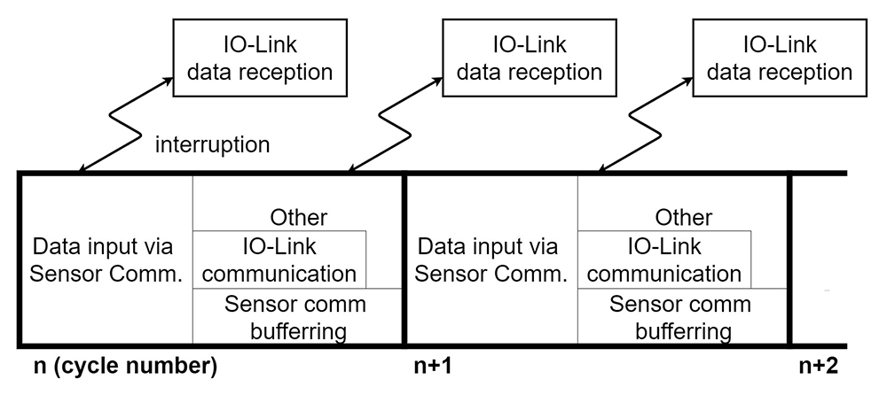
During the “Data input via Sensor Comm.”, the reception processing for sensor-to-sensor communication is performed. In this communication, reception occurs of the sensorʼs internal status and log information, in other words, the data transmitted to the IO-Link master, while transmission occurs of external input information to the primary light receiver. If a request comes in for IO-Link communication during this processing, only communication data acquisition will be performed through the interrupt process to prioritize sensor-to-sensor communication. During the “Other” category portions, the handling of the IO-Link communication occurs along with such events as external input processing or indicator lamp control.
If a request comes in for sensor-to-sensor communication during this processing, communication data will be saved in the temporary memory until the subsequent “Data input via Sensor Comm.”, during which data processing and reply processing occur. From out of consideration to the volume and frequency of each data communication and the buffer size for each data reception, their respective required processing times are defined into their own timetables, according to which each data is processed. In this way, delay-free communication is performed with communication masters that use multiple protocols.
The whole system, including the sensor-to-sensor communication explained above, has passed both in-house evaluations by in-house criteria reflecting the product specifications and the applicable safety standards and external third-party evaluations. These evaluations include noise, temperature, other environmental resistance evaluations, and a communication load evaluation.
5. Conclusions
Conventional safety light curtains are connected via their output on/off information to production systems. Maintenance information is, however, processed through dedicated tools, whereby direct interfacing has been difficult between safety light curtains and production systems. The technology presented herein uses a product known as an intelligent tap to enable interfacing with general-purpose networks, so far impossible with conventional safety components, through open protocol communication while retaining the conventional means.
Note, however, that safety components are categorized as input, logic, or output components. A safety light curtain is an example of an input element. Hence, our next challenge is to deploy the technology presented herein to the size and cost reduction of safety components other than safety light curtains and produce effects comparable with those achievable as this technology is deployed to safety light curtains. The deployment of this technology to safety door switches, for example, will lead to further improving the coverage of informatizable devices.
This study established a method of converting data in safety components into non-safety information to be notified to general-purpose networks. Unsure of the market needs for informatized safety networks, we chose general-purpose networks. From now on, we intend to consider actively using informatization in safety networks along with horizontal deployment of the technology presented herein. From now on, we intend to create a new value of informatization achievable through interfacing with safety networks and help our customers further improve their production operating rate.
References
- 1)
- OMRON Corporation, “Future Factory” (webpage in Japanese), https://www.fa.omron.co.jp/product/special/sysmac/overview/iot-future-factory.html (accessed: June 26, 2020).
- 2)
- OMRON Corporation, “Introduction to Sysmac - IoT” (webpage in Japanese), https://www.fa.omron.co.jp/product/special/sysmac/introduction-to-sysmac/visualization.html (accessed: June 26, 2020).
- 3)
-
OMRON Corporation, “Sysmac Concept” (webpage in Japanese), https://www.fa.omron.co.jp/product/special/sysmac/concept/
(accessed: June 26, 2020). - 4)
- Safety of machinery - Safety-related parts of control systems - Part 1: General principles for design, ISO 13849-1:2015, International Organization for Standardization, 2015.
- 5)
- Functional safety of electrical/electronic/programmable electronic safety-related systems - Part 1: General requirements, IEC 61508-1 Ed. 2.0:2010(b), International Electrotechnical Commission, 2010.
- 6)
- Electro-sensitive protective equipment - Part 1: General requirements and tests, IEC 61496-1 Ed. 3.0:2012(b), Safety of machinery, International Electrotechnical Commission, 2012.
The names of products in the text may be trademarks of each company.