


Development of Small Size, Lightweight, High Efficiency Outdoor Single Phase Solar Inverter
- Solar inverter
- Downsizing and weight reduction
- High efficiency
- Two phase interleaved boost chopper
Photovoltaics is attracting attention because it reduces the global environmental load and improves the energy self-sufficiency rate. However, the power generation cost of photovoltaics in Japan is about 1.6 times higher than that of the world’s weighted average in 2017, and further promotion and spread of photovoltaics requires a reduction of the power generation cost.
We have newly developed and commercialized the KPV-A and KPW-A series of outdoor single phase solar inverters. The KPV-A and KPW-A series have achieved a small lightweight size and high efficiency by employing an advanced two-phase interleaved technology, a high frequency switching technology, and optimization of the grid control. As a result, we have realized a solar inverter with a weight of 20 kg, which enables installation work by one person. We have also realized high power conversion efficiency solar inverters with 95.5% at low output power around 500 W and 96.0% at the rated output power. Therefore, it is possible to reduce the initial introduction cost by improving workability and to maximize the total power generation by improving conversion efficiency. They can be expected to contribute to promotion and spread of photovoltaics.
In this paper, we report the small lightweight size and high efficiency technology on the KPV-A and KPW-A series.
1. Introduction
Since the 2011 Great East Japan Earthquake, the ratio of nuclear power generation in the amount of domestically generated electricity has remained low, resulting in an increased dependence on thermal power generation. It is feared that the increased ratio of thermal power generation may lead to increased carbon dioxide emissions, higher fuel procurement costs, a higher dependence on the Middle East for oil imports, and hence reduced stability in fuel procurement. Accordingly, in 2015, Japan established the Long-Term Energy Supply-Demand Outlook (Energy Mix) as a national energy policy1). The Energy Mix lays down a 2030 target power source composition, which expects all fossil fuels combined (petroleum, coal, and LNG) to account for approximately 56% in the total generated energy, nuclear power for about 20% to 22%, and renewable energies of hydro, wind, and solar-generated power for about 22% to 24%. Expectations are running high on renewable energies in particular because they help to cut carbon dioxide emissions, reduce the fuel procurement cost in thermal power generation, and achieve higher energy self-sufficiency. As of 2016, however, renewable energies accounted only for approximately 15% of the total installed capacity, thus requiring further promotion and the spread of renewable energies.
Following the implementation of the Excess Electricity Purchasing Scheme and the All-quantity Buyback Program in 2009 and 2012, respectively, photovoltaics showed the sharpest increase in the penetration rate among renewable energies. However, the power generation cost of photovoltaics in Japan is about 1.6 times higher than that of the worldʼs weighted average in 2017, and the further promotion and spread of photovoltaics requires a reduction of the power generation cost. The power generation cost depends on the total cost covering all the costs, including the fuel cost, incurred during the period from the installation of the plant through maintenance to removal or decommissioning and on the gross generation available during the service life of the plant. In the case of photovoltaic power generation, which incurs no fuel cost, the total cost is accounted for, for the most part, by the initial investment cost. The initial investment cost of photovoltaics is high in Japan. In Japan, it costs approximately 3.7 times more to implement photovoltaics than in Germany, a leader in photovoltaic power generation. The challenge posed is to reduce the types and quantities of members to be installed and the number of person-hours required for installation work2). Another challenge is to reduce the power generation losses during the service life of photovoltaic systems to increase the gross generation.
For further promotion and the spread of photovoltaics, we have developed solar inverters that export solar power to the grid power supply by maximizing the electric power generated by solar batteries and converting the DC power obtained therefrom into AC power for use in the grid power supply. In 2016, we developed and commercialized the KPM2 series of outdoor single-phase solar inverters featuring high flexibility in solar battery design, an enhanced resistance to the environment, and an improved installability.
The following chapters of this paper report on the KPV-A and KPW-A series of outdoor single-phase solar inverters developed and commercialized with a smaller, more lightweight body, higher efficiency, better installability at lower cost than their KPM2 series counterparts to reduce the power generation cost through the maximization of gross generation.
2. Specifications and features of the solar inverters
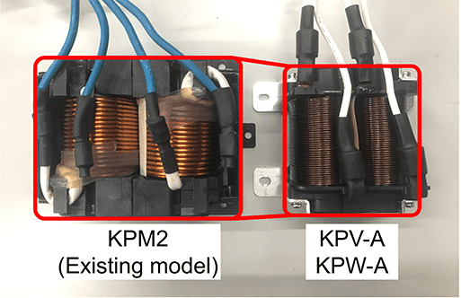
Fig. 1 shows the external views of the KPV-A and KPW-A series, while Table 1 compares their specifications with those of the KPM2 series.
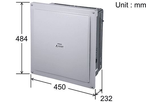
The KPV-A and KPW-A series use the same housing and hence externally appear identical to each other. The KPV-A series was commercialized for industrial applications that include use as solar power generation systems for outdoor installations, while the KPW-A series was commercialized for household use at detached houses, small-size factories, and other similar locations and for installation in buildings for industrial use.
The rated output capacities available are 5.5 kW for the KPV-A series and 4.8 kW and 5.5 kW for the KPW-A series. The product lineups of both the KPV-A and KPW-A series include models resistant to heavily salt-laden air, which support installation in salt damage-prone areas within 500 m from the shore or at seaside locations not directly exposed to sea spray, to overcome the restrictions on their installation.
| Item | KPV-A | KPW-A | KPM2 (conventional) |
|
|---|---|---|---|---|
| Capacity | 5.5 kW | 5.5 kW/4.8 kW | 5.5 kW/4.4 kW | |
| DC input | Maximum operating input current | 4 lines: 40 A (10 A/circuit) 3 lines: 33 A (11 A/circuit) |
4 lines: 44 A (11 A/circuit) | 4 lines: 38 A (9.5 A/circuit) |
| Maximum permissible short-circuit current | 4 lines: 44 A (11 A/circuit) 3 lines: 36 A (12 A/circuit) |
4 lines: 48 A (12 A/circuit) | 4 lines: 44 A (11 A/circuit) | |
| AC output | Rated output (continuous) | 5.5 kW (power factor = 0.95/1.0) | 5.5 kW/4.8 kW (power factor = 0.95/1.0) | 5.5 kW/4.4 kW (power factor = 1.0) |
| Power conversion efficiency | 96.0% (power factor = 0.95/1.0) | 96.0% (power factor = 0.95/1.0) | 94.5%/95.0% (power factor = 1.0) | |
| Outer dimensions (W×H×D) | 450×484×232 mm | 450×484×232 mm | 720×400×220 mm | |
| Weight (main body) excl. mounting baseplate |
20 kg | 20 kg | 31 kg | |
| Safety distance (right and left) | 3 cm | 3 cm | 15 cm | |
Moreover, equipped with an output control capability, newly specified as a method of grid power supply stabilization against a mass introduction of photovoltaics, and AICOT®(Anti-Islanding COntrol Technology), which is a new method of active detection of islanding operation (frequency feedback method with step injection of reactive power) developed as our proprietary technology ahead of the rest of the industry and included as a requirement of the Grid-interconnection Code, the KPV-A and KPW-A series comply with all currently effective standards3).
The main features of the KPV-A and KPW-A series are as follows:
- (1) Available with high power conversion efficiencies of 95.5% at a low output of approximately 500 W and 96.0% at the rated power for the maximization of gross generation
- (2) Conforming to the specified maximum permissible shortcircuit current of 12 A/circuit, supporting connection to high-efficiency, high-current type solar batteries
- (3) The KPV-A and KPW-A series meet the specified overload rates of 200% or more and 250% or more, respectively, to generate more electricity from smaller amounts of insolation in mornings and evenings or under cloudy weather conditions
- (4) Available with a bodyweight of 20 kg and hence installable by one person; this improved installability is coupled with a smaller footprint achieved by reduced right and left safety distances from surrounding installed objects or between adjacent units and by reduced outer dimensions, thereby helping to reduce the types and quantities of members to be installed, such as cables, and hence the initial investment cost
3. Configurations of the solar inverters
Fig. 2 shows a typical circuit configuration of the KPV-A and KPW-A series:
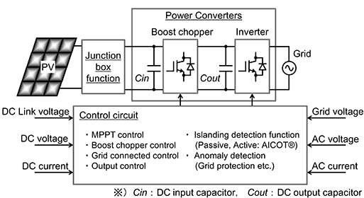
A KPV-A or KPW-A series solar inverter consists of a junction box function unit consisting mainly of switches and blocking diodes, a boost chopper or an inverter used as a power converter, and a control circuit unit used for grid power supply protection and power converter control. The boost chopper uses maximum power point tracking control (MPPT) to maximize and export the electric power generated by solar batteries to the inverter. The inverter converts the DC power output from the boost chopper into AC power and uses grid control to export the AC power to the grid power supply to suit the voltage, frequency, and other conditions of the grid power supply. The control circuit unit is equipped with a variety of system protection functions, such as MPPT control, boost chopper control, grid control, output control, AICOT® islanding operation detection, and anomaly detection.
4. Developed technologies
The KPV-A and KPW-A solar inverters developed this time achieved a size and weight reduction of 80% by volume and 64% by weight as compared with the conventional KPM2 series models. Moreover, the KPV-A and KPW-A series solar inverters provide higher efficiency through a power conversion efficiency improvement of 3.2% at a low output of 550 W and 1.5% at the rated power of 5,500 W compared with the conventional KPM2 series models.
A large portion of the power loss incurred in a solar inverter is accounted for by its power converter. The KPV-A and KPW-A series provide higher efficiency through the reduction in the power loss of the boost chopper that doubles as a power converter. Among the components constituting a solar inverter, its reactors account for the largest part of its volume and weight. The reactors and the semiconductor devices constituting the power converter are heat-generating parts that reach high temperatures. Therefore, a cooling structure is necessary to release the heat generated by the reactors and semiconductor devices to the outside air. Besides the reduced size and weight of the reactors, KPV-A and KPW-A series achieved a reduction in the power losses induced by the semiconductor devices in the boost chopper and hence the amount of heat generation. This achievement allowed the size and weight reduction of the cooling structure and led to a solar inverter with smaller overall outer dimensions and a smaller bodyweight.
The specific technical elements developed to provide a small, lightweight body and a high efficiency to the KPV-A and KPW-A series are as follows:
- (1) Small-size and lightweight technology for the DC reactor, achieved through the employment of a two-phase interleaved boost chopper (hereafter “two-phase boost chopper”) and a high frequency switching technology
- (2) High-efficiency technology for the solar inverter, achieved through the employment of the two-phase boost chopper, as well as its ability to switch the number of operating circuits and select between two switching frequencies of the two-phase boost chopper to suit the input-current and input-power domains
- (3) Small-size and lightweight technology for the AC reactor as a constituent of the inverter unit, achieved through a robust grid control
The following sections describe the technologies developed for the boost chopper unit and inverter unit, respectively.
4.1 Small size and lightweight technology for the DC reactor in the boost chopper unit
The conventional KPM2 series models are equipped with a boost chopper of a single-phase configuration (hereafter “single-phase boost chopper”).
Fig. 3 shows a typical circuit configuration of the single-phase boost chopper:
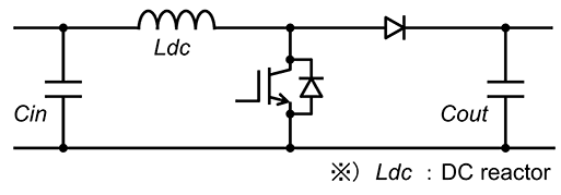
The single-phase boost chopper consists of semiconductor devices and a DC reactor Ldc. The magnitudes of input and output current ripples caused by the switching operations of the semiconductor devices depend on the inductance value of the DC reactor and the switching frequencies of the semiconductor devices. When compared at the same switching frequency, the magnitudes of input and output current ripples are smaller on the side with a larger inductance value and vice versa. Connected to the input of the boost chopper is the DC input capacitor Cin to reduce the solar battery voltage fluctuations caused by variations in variations in illuminance. Meanwhile, connected to the output of the boost chopper is the DC output capacitor Cout for DC-link voltage smoothing required for the inverter connection to the grid power supply. Input and output current ripples must be limited to the desired magnitude to meet the internal temperature increase specifications and design life expectancies of the input and output capacitors. The conventional KPM2 series models were designed to set a high inductance value for their DC reactor to obtain desired magnitudes of input and output current ripples.
The electric current specification of the DC reactor is one of the specifications that significantly affect its outer dimensions and weight. In the case of the single-phase boost chopper, the steady-state mean current flowing through the DC reactor is equal to the current generated by the solar battery. Our solar inverters are of high-efficiency type and have an input current specified to support high-current type solar batteries; this means that in the conventional KPM2 series models, a mean current of up to 44 A flows through their DC reactor. Accordingly, the electric current specified for their DC reactor was rated to the maximum current of the solar battery. Thus, their DC reactor was designed as a high-current type to withstand the maximum mean current of 44 A.
As explained above, for the conventional KPM2 series models, the electric current specification for their DC reactor was designed to the maximum current of the high-current type solar battery; besides, the design inductance value was used to limit the magnitudes of input and output current ripples. Consequently, a large DC reactor resulted.
For the KPV-A and KPW-A series developed this time, a two-phase boost chopper was adopted. Fig. 4 shows a typical circuit configuration of the two-phase boost chopper. Featuring a configuration in which two single-phase boost choppers for conventional models are connected in parallel with each other, the two-phase boost chopper provides two major advantages for the size and weight reduction of the DC reactor.
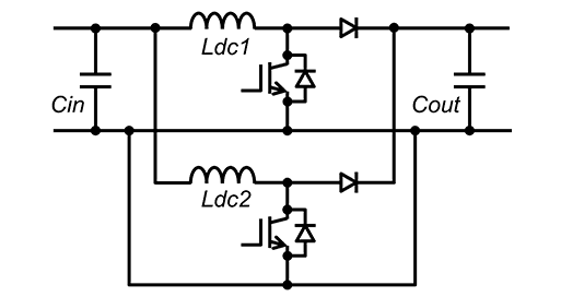
The first is that the dual-circuit boost chopper shifts its carrier phase by 180 degrees between its two circuits so that the input and output current ripples occurring in the two circuits will offset each other, thereby reducing the current ripples flowing into the input and output capacitors. As a result, the inductance value of the DC reactor can be set smaller than that of a single-phase boost chopper. The second is that the current generated by the solar battery can be shunted by the dual-circuit boost chopper, which allows a reduction in the electric current specified for the DC reactor. To take full advantage of the above two advantages, however, the electric current generated by the solar battery must be appropriately balanced between the two boost-chopper circuits. An occurrence of current unbalance between the two circuits would not only result in failure to offset the input and output current ripples between the circuits, hence causing an increase in input and output current ripples, but could cause the current flowing through the DC reactor to exceed the value specified therefor. Therefore, a current balance control for ensuring a proper current balance between two circuits was added to the boost chopper control.
Moreover, besides the adoption of a two-phase boost chopper, one of the boost chopper switching frequencies was increased twice higher than before to achieve a further reduction of the inductance value of the DC reactor. As shown above, the DC reactor for the KPV-A and KPW-A series achieved a size and weight reduction through the employment of a two-phase boost chopper, the addition of current balance control, and the adoption of a high frequency switching technology.
4.2 High-efficiency technology
Fig. 5 shows the switching domains for switching the number of operating circuits of the two-phase boost chopper and selecting between its two switching frequencies:
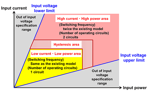
A two-phase boost chopper has two circuits between which a current generated by a solar battery can be shunted. Therefore, assuming that the resistance component per circuit of the two-phase boost chopper is equivalent to that of a single-phase boost chopper, conduction loss, which is determined by I2R, is reduced by half. Hence, in the high-current/high-power domain, in which conduction loss accounts for a large portion of its total power loss, the two-phase boost chopper provides higher efficiency to a solar inverter. The two-phase boost chopper, however, has a larger number of operating circuits than a single-phase boost chopper and hence has the drawback of increased switching losses by semiconductor devices. Moreover, with one of the boost chopper switching frequencies increased twice as much as before to reduce the DC reactor size and weight, the iron loss in the DC reactor has increased along with increased switching losses in the semiconductor devices. Accordingly, in the low-current/ low-power domain where the iron loss of the DC reactor and the switching losses of the semiconductor devices account for a large part of the power loss of the two-phase boost chopper as a whole, the number of operating circuits of the two-phase boost chopper was reduced from two to one to stop the switching operation of one circuit. Additionally, the boost chopper switching frequency in the low-current/low-power domain was reduced to the same switching frequency of the conventional modelsʼ boost chopper to prevent the deterioration of the iron loss of the DC reactor and the switching losses of the semiconductor devices. Furthermore, a hysteresis domain was set between the low-current/low-power domain and the high-current/ high-power domain, so that no chattering would occur in the switching of the number of operating circuits or the selection between the two switching frequencies even if the electric current and power generated by solar batteries fluctuated because of the variations in illuminance.
Although the power loss of the two-phase boost chopper can be reduced in the low-current/low-power domain by limiting the number of operating circuits and reducing the switching frequency, an increase may occur in the number of current ripples flowing into the input and output capacitors. In the low-current/low-power domain, however, the operating mode of the boost chopper is the discontinuous current mode that clamps the current ripples flowing through the DC reactor to a zero current. Besides, the output power exported back to the grid power supply is small. Therefore, a decrease occurs in the number of current ripples flowing into the input and output capacitors. Besides, because of the DC superposition characteristics matching the magnetization curves for the magnetic materials constituting the DC reactor, the inductance value is higher in the low-current/low-power domain than in high-current/high-power domain. Hence, a reduced amount of current ripples can be expected. With these characteristics taken into account, the number of operating circuits of the boost chopper and its switching frequency are both properly switched to suit the input-current and input-power domains, so that the input and output capacitors will meet their internal temperature rise specifications and design life expectancies.
The KPV-A and KPW-A series are our first outdoor single phase solar inverters equipped with the above technical elements to provide high-efficiency in all the domains from the low-current/low-power domain to the high-current/high-power domain.
4.3 Small size and lightweight technology for AC reactor in the inverter unit
Fig. 6 shows a typical circuit configuration of its inverter output module interconnected to the grid.
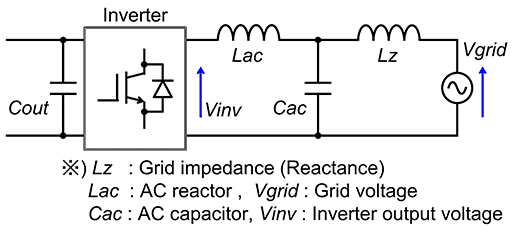
Because the solar inverter is connected with the grid power supply, its inverter output module is connected to the power distribution equipment connected to power transmission and distribution networks or with an AC reactor Lac and AC capacitor Cac that reduces harmonic currents and protects common loads from their negative impacts. Additionally, grid impedances, including reactance component Lz, such as pole transformer impedances and line impedances in power transmission and distribution systems, exist in the grid power supply to which the solar inverter is connected. Unusually large grid impedances may occur in such cases as when a solar power generation system for outdoor installation on a site converted from an idle or agricultural land is installed in an area poorly covered by power transmission and distribution networks and distant from power distribution equipment, such as pole transformers. When the grid impedance exceeds the ratio of the impedance formed by the AC reactor and AC capacitor of an inverter, mutual interferences may occur between the grid impedance and the AC reactor and AC capacitor of the inverter, destabilizing the grid control of the inverter 4)5). In the conventional KPM2 series models, a high inductance value was set for their AC reactor to make the grid control robust against destabilization. This setting resulted in an increase in the AC reactor size.
Fig. 7 shows a typical configuration of grid control:
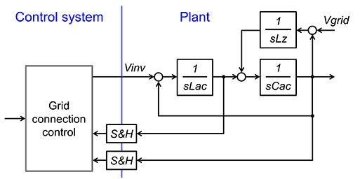
For the KPV-A and KPW-A series, the control constant was optimized through a review and a stability analysis of the configuration of the grid control to provide the required level of disturbance reduction performance and improve the robustness of the grid control. As a result, a smaller, more lightweight AC reactor was obtained with an inductance value reduced by half compared with that of the AC reactor for the KPM2 series.
5. Development results
Fig. 8 shows the external views of the DC reactors for the KPM2 series and the KPV-A and KPW-A series:
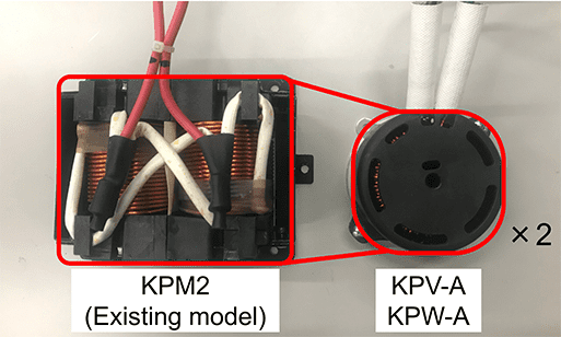
The KPV-A and KPW-A series use the same pair of identical DC reactors. The KPM2 series models contain a DC reactor with a volume of 0.93 L and a weight of 2.5 kg, while the KPV-A and KPW-A series use two identical DC reactors with a total volume of 0.6 L and a total weight of 1.6 kg. As a result of the reduction in their inductance value and required current through the employment of a two-phase boost chopper, the addition of current balance control, and the adoption of high frequency switching technology, the DC reactors for the KPV-A and KPW-A series achieved a size and weight reduction of 65% by volume and 64% by weight. Fig. 9 shows the external views of the AC reactors for the KPM2 series and the KPV-A and KPW-A series:
The KPV-A and KPW-A series use the same AC reactor. The KPM2 series models has an AC reactor with a volume of 0.93 L and a weight of 2.6 kg, while the KPV-A and KPW-A series have an AC reactor with a volume of 0.59 L and a weight of 1.8 kg. As a result of the reduction in its inductance value by half through the enhancement in the robustness of grid control, the AC reactor for the KPV-A and KPW-A series achieved a size and weight reduction of 63% by volume and 69% by weight.
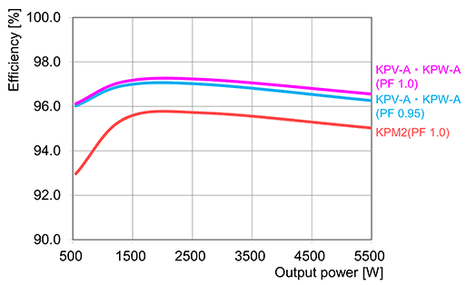
Fig. 10 compares the KPM2 series with the KPV-A and KPW-A series in terms of power conversion efficiency at a solar battery voltage of 320 V, a grid voltage of 202 V, and a grid frequency of 60 Hz. As a result of the adoption of a two-phase boost chopper, the addition of a switching function for the number of operating circuits, the inclusion of a switching frequency selection function, the KPV-A and KPW-A series outperform the conventional KPM2 series models by 3.2% at a low output of 550 W and by 1.5% at the rated power of 5,500 W, thereby achieving significant improvements in power conversion efficiency in all domains from the low-current/low-power domain to high-current/high-power domain.
As shown above, besides the reduced size and weight of the reactors, the KPV-A and KPW-A series achieved a reduction in the power loss of the boost chopper, resulting in a size and weight reduction to a body volume of 51 L and a bodyweight of 20 kg as compared with 63 L and 31 kg of the KPM2 series.
6. Conclusions
This paper presented the KPV-A and KPW-A series outdoor single-phase solar inverters made available with a smaller, more lightweight body and a higher efficiency. The KPV-A and KPW-A series achieved a size and weight reduction in the reactors, conventionally large components, and a power loss reduction in the boost chopper, through the employment of a two-phase boost chopper and a high frequency switching technology and through the optimization of grid control. This led to the realization of a small, lightweight solar inverter with a main body 51 L in volume, 20 kg in weight, and high power conversion efficiencies of 95.5% at a low output of approximately 500 W or 96.0% at the rated power. The KPV-A and KPW-A series have achieved a higher installability through size and weight reduction and higher power conversion efficiency in all power domains and hence can help reduce the initial investment cost and maximize the gross generation. Therefore, these series enable reducing the power generation cost of photovoltaics and are expected to help further promotion and spread of photovoltaics.
To contribute to the realization of a sustainable society, we intend to continue developing solar inverters able to promote renewable energies and meet further social needs.
References
- 1)
-
Agency for Natural Resources and Energy, Ministry of Economy, Trade and Industry, “Long-Term Energy Supply-Demand Outlook” (in Japanese),
https://www.enecho.meti.go.jp/committee/council/basic_policy_subcommittee/mitoshi/pdf/report_01.pdf (accessed Apr. 26, 2019). - 2)
-
Japan Photovoltaic Energy Association, “Towards Photovoltaics as an Independent, Major Power Source” (in Japanese),
http://www.jpea.gr.jp/pdf/t180418_2.pdf (accessed Apr. 26, 2019). - 3)
- Japan Electrical Manufacturersʼ Association, “Detection Method for Standard Active Islanding Operation of Single Phase Solar Power Inverters for Distributed Power Supply (Frequency Feedback Method with Step Injection of Reactive Power),” JEM 1498, p-30, 2017.
- 4)
- K. Yuhki, N. Takeo, Z. Toshiyuki, and U. Takeshi, “A Compensator that Negate the Influence of Grid Impedance based on Frequency Sweep Estimation Technique”. OMRON TECHNICS, vol. 161, pp. 54-59, 2018.
- 5)
- K. Yuhki, N. Takeo, U. Takeshi, and Z. Toshiyuki, “Unique Self-Tuning Method for Stability of Grid-Connected Inverter,” in Proc. IEEE International Conference on DC Microgrids, May 2019.
AICOT® is a registered trademark of OMRON Corporation.
The names of products in the text may be trademarks of each company.