


Advancing Automated Assembly–Team O2AC at the World Robot Summit 2020
When installing robot systems in manufacturing applications, only 20 to 30% of the cost is due to the hardware, while more than 50% of the cost comes from system integration, such as setting up, programming and connecting peripheral devices into a unified system. Given the labor shortages both in Japan and worldwide, robot systems that can handle a variety of products with low production volumes are strongly desired. We participated in the World Robot Summit (WRS) Industrial Category to move towards its proclaimed goal of “agile one-off manufacturing”, and aimed to build a production system that can respond quickly, leanly and without waste to various changing production requirements, thereby realizing the “manufacturing of the future”.
Together with other organizations, we formed a team and have been working since 2018 on a system that is robust to changes in parts and assembly positions, without using parts-specific jigs or teaching. We have continuously improved the system by tackling issues that came to light at the pre-convention (WRS2018) and other events, where we obtained the SICE Special Award. In addition, we participated in the WRS2020 (postponed to 2021 due to Covid-19) as Team O2AC and obtained 3rd place as well as the Artificial Intelligence Society Award.
In this article, we describe our approach to solving the assembly problem, the hardware and software technologies we used to implement our solution, and the lessons we learned during the development.
1. Introduction
Automated assembly with robotic arms is highly challenging, as it places high requirements on the physical robot system, as well as the software implementation. Due to the tight part tolerances, it requires high mechanical precision and fine control. Because of the many interlocking steps in the assembly process which can change according to part measurements and positions, it is laborious to program the motions (“teach”) manually.
Commonly, assembly tasks are realized by building parts-specific jigs, which ensure that each part is in a known position, so that the process can be repeated by the robot in an identical manner. However, the cost and size of these jigs makes it intractable to use the same robot system for many different types of products, or to change from one product to another.
In order to advance towards jigless and teachless assembly, we built a system for the World Robot Summit 2020 Assembly Challenge with Team O2AC (OMRON SINIC X, OMRON, Osaka University, AIST, Chukyo University). We obtained the 3rd place (with only 2 points to the 2nd place) and an award from the Japanese Society for Artificial Intelligence. In this article, we describe our approach and lessons drawn from the development.
2. System Design
As our goal was to test the limits of and challenges in current jigless and teachless assembly, we teamed up with universities and research institutions which did not have access to and/or experience with industrial hardware. To collaborate efficiently and immediately start working productively, we decided to build our prototype 1) using ROS-based open software, and 2) as a lean robot manipulation system that will stay useful beyond the WRS, with little to no hardware customization. This minimized the time spent on hardware implementation, allowed the use of public, reviewed code and made collaboration significantly more efficient.
The code running our system is public and can be found at https://github.com/o2ac/o2ac-ur
2.1 Hardware–Two arms with hand-held tools
After having built a prototype with 3 arms in 20181,2), for the WRS2020 we decided to make the system as lean as possible. We used only two generic robot arms equipped with a parallel gripper and wrist cameras, together with hand-held tools and parts feeders/holders. Fig. 1 shows the complete robot system.
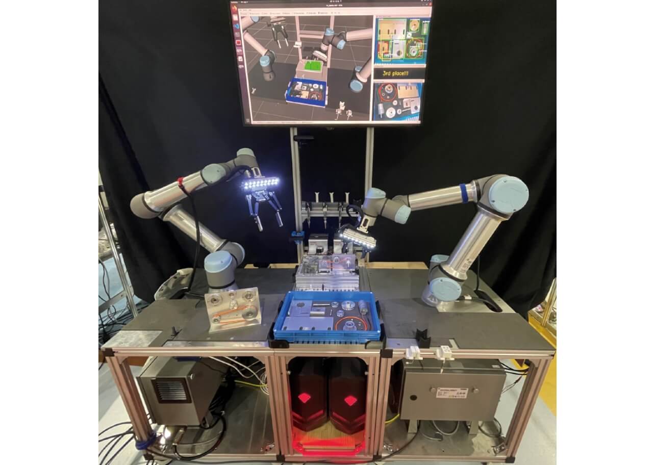
The system was controlled by two PCs, running an Ubuntu real-time kernel and Nvidia CUDA drivers respectively. This allowed both high-speed robot control as well as neural-network based computer vision algorithms.
We also used hand-held tools which are described in section 5.
2.2 Software–Rapid prototyping and collaboration
We used ROS, MoveIt and other open-source software to drive our solution. The system is encapsulated in a Docker container, which can be downloaded and run on any Ubuntu PC (18.04+). This allowed us not only to collaborate quickly and efficiently with our external collaborators, but also to use existing open code and drivers rather than writing custom ones, which accelerated our development and prototyping speed.
Among the packages and code we developed or used:
- –
- An assembly database which generates target part positions based on their CAD models, so that motions are updated automatically according to part specifications
- –
- A symbolic planner that tracks uncertainty (see section 3) and generates actions that reliably position the part in known positions, even in environments with high levels of noise
- –
- A computer vision system (see section 4) that uses neural networks, image processing and CAD matching to determine the position of parts as well as the success/failure of assembly operations
- –
- A hybrid force-position controller applicable to any 6-DOF robot arm, which succeeded on all the insertion tasks in the competition
If you use our framework, you can define how parts are assembly and display how parts like Fig. 2.
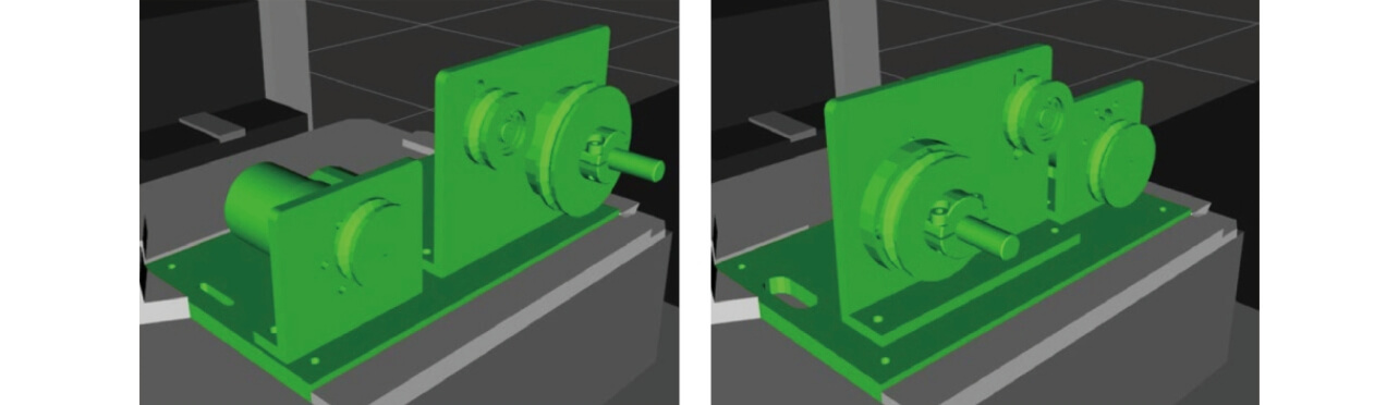
Robot motions are adjusted automatically. Left: Standard. Right: Surprise Plus.
Notably, we developed a scheduler for MoveIt which allows simultaneous planning and execution with multiple robot arms, and which ensures safety even for overlapping workspaces. This reduced overall execution time by 20–40% and opened up new avenues for operating even more efficiently in multiple tasks.
3. Uncertainty-aware Manipulation
When detecting an object using computer vision, the result is always subject to an unavoidable amount of noise and uncertainty. Conventional approaches attempt to work around this by using expensive sensors, very rigid and precisely manufactured robot bases, and complicated calibration procedures.
By contrast, we accept that some uncertainty cannot be avoided, and integrate it into our planning and design process. As shown in Fig. 3, we associate every object pose result obtained from vision with an uncertainty, which is reduced only in the course of manipulation. Actions such as grasping and pushing the object limit the possible positions, and gradually reduce the uncertainty until the position is known with high precision and certainty.
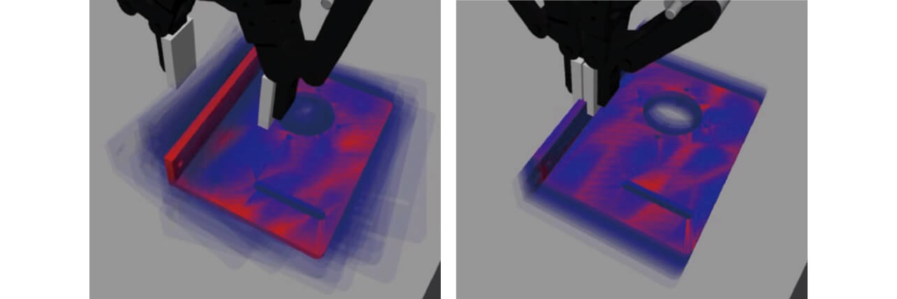
Left: Before the grasp, many positions are possible. Right: After the grasp, the possible positions are restricted.
3.1 Planning with uncertainty and the environment
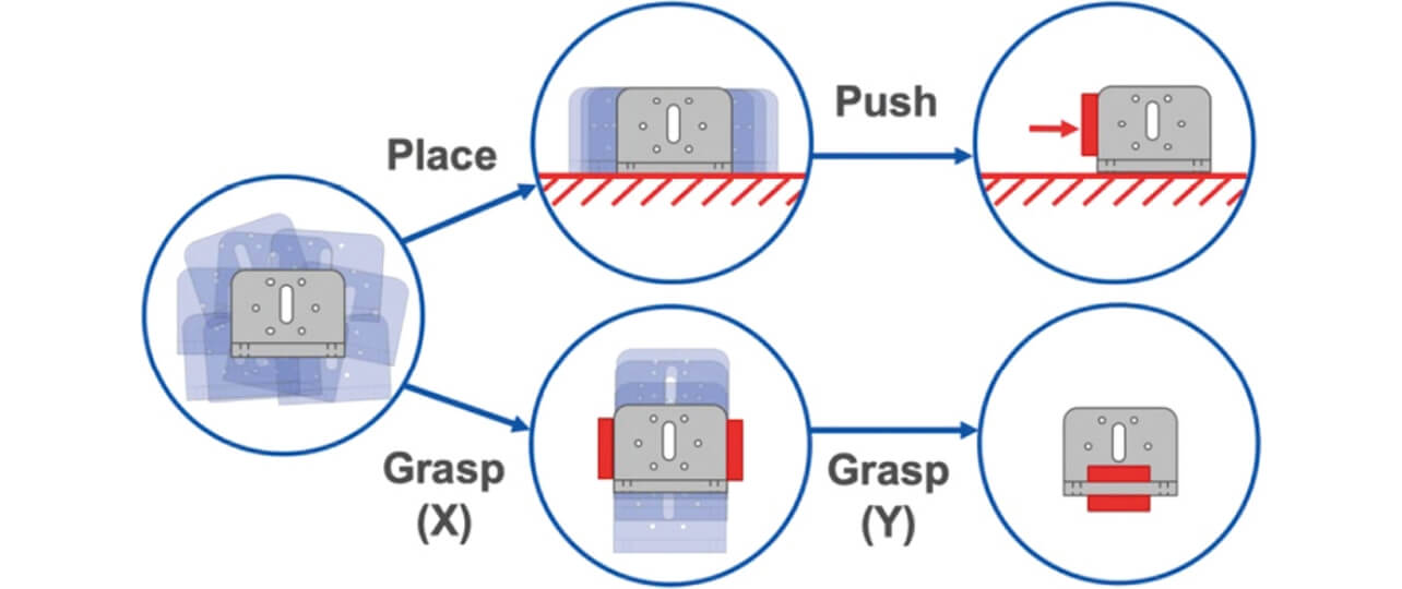
In our previous papers 3), we have proposed different actions to reduce the uncertainty of grasped objects. In a paper that we are currently preparing, we extend these actions to include extrinsic manipulation, such as releasing the object from the gripper, pushing it with the gripper, or lightly grasping the object while pushing it into an obstacle. These actions are highly effective and have been used in multiple occasions in the competition.
Based on these actions, we have built a planner which generates action sequences that succeed reliably even if the object position has an error of multiple millimeters. Rather than fine-tuning each position, the system generates full motion sequences to perform assembly procedures. These sequences can then be inspected and optimized by the user, which makes programming and teaching significantly easier. Fig. 4 shows example planning results.
4. Computer Vision
We are using a combination of computer vision techniques, based on both 2D and 3D image data obtained from the robots’ wrist-mounted cameras. The cameras are consumer-grade (Intel Realsense SR305), which limits the maxium precision of the vision pipeline. However, as described in the previous section, our approach accepts this uncertainty and achieves precise positioning even with very affordable sensors.
4.1 Tray picking
We used a combination Single-Shot MultiBox Detector4) and 3D Localization (Fig. 5-1). (TODO: Cite the paper) A common difficulty with neural-network based approaches is the sensitivity to lighting conditions. Due to both COVID-19 and the distributed nature of our team, we had to tackle the robustness of our vision system early on, as the lighting in the OMRON SINIC X office and the laboratory in Chukyo University was very different. As a result, our system was very robust to different lighting conditions, and we experienced practically no difficulty with the conditions at the competition site.
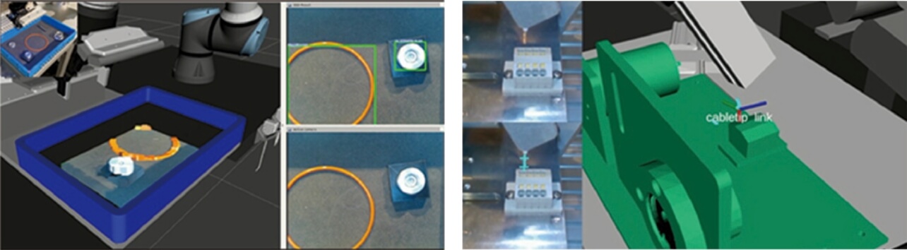
Fig5-1: Parts being recognized in the tray (using neural networks)
Fig5-2: Cable tip detection (using background subtraction)
In fact, the RGB-based parts detection was so robust that it often outperformed the 3D-point-cloud-based recognition routines. In retrospect, it would have been very worthwhile to encode the rotation angle of parts in the network, to make use of the high speed of the network.
4.2 Bearing orientation
Unlike scene-mounted cameras mounted on the work cell’s ceiling, the wrist-mounted cameras allow close-up views of assembled objects. As shown in Fig. 6, the bearing is inspected after insertion, to ensure that the holes align with the screws’ target positions. If they do not match, the bearing is rotated in-place by the required amount.
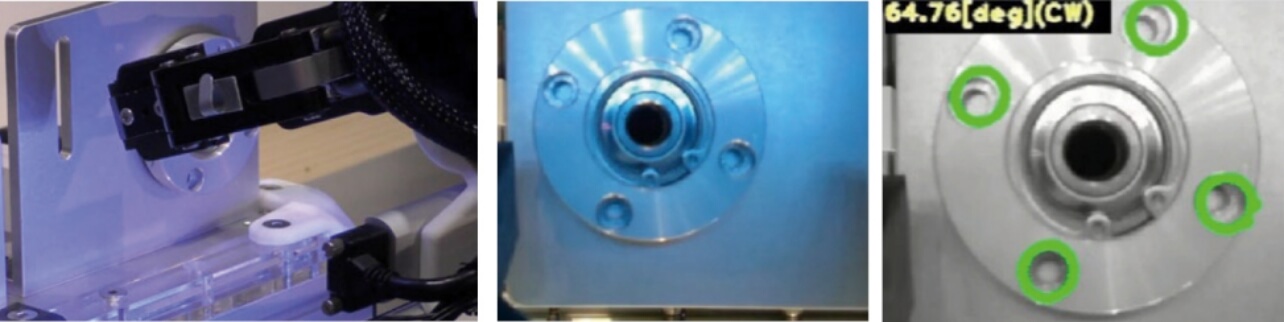
Left: Camera facing the bearing. Middle: Camera view. Right: Vision result (angle offset from edge detection)
4.3 Cable detection
As the cable is highly deformable, the position of the tip cannot be predicted reliably, and detecting it in an unstructured environment is highly difficult. We solve this problem by first executing a synchronized collaborative motion with both robot arms, which cages the cable and places the tip in one of the robots’ grippers. Then, we use background subtraction to find the tip of the cable in the image and project it back into 3D space (Fig. 5-2).
5. Compliant, hand-held tools
Instead of using expensive and specialized tool-changers, we used tools that were grasped by the gripper, as a human hand would. These tools were of three different types, as shown in Fig. 7:
- –
- Suction-equipped screw tools, with compliance (using precision parts from SAWA Ltd.)
- –
- 3D-printed screw tools with compliance, but without suction
- –
- Passive tools (e.g. hooks, plungers)
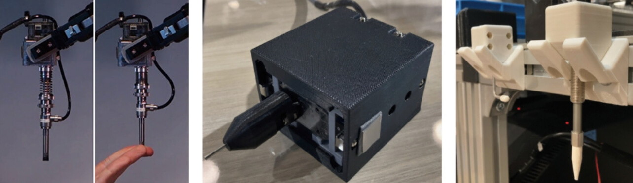
Middle: Screw tool with compliance and without suction. Right: Passive tools.
The screw tools were driven by small Dynamixel motors with torque control. Combined with the suction pressure sensor, this allowed the detection of both motor stalling and screw contact, which we used to determine successful fastening of screws.
However, some tools that were used for specific manipulations, just like crochets used by humans, did not need to be actuated. For example, we used a hook tool to thread the belt around the pulleys, and a plunger tool to separate items that were packed too tightly to be picked.
The screw tools and plunger used physical compliance in order to apply light pressure to the environment. As a comparable level of compliance would require a very high control frequency if generated by the robot’s joint actuators, physical compliance allows the use of affordable robots, while ensuring high reliability and performance.
6. Lessons
One significant difficulty that we had hardly encountered during testing occurred frequently in the competition: screws becoming stuck in the thread before the fastening is finished. We determined the success of the fastening procedure on the basis of the pressure sensor and torque control in our screw tools, but this ended up being insufficient.
To ensure that the screw was flush after fastening, we should have used the wrist camera to confirm screwing success. The wrist camera could have also been used to track the tool tip and implement a fallback procedure. This cost us a significant amount of points during the final days of the competition and would surely have obtained the 2 points separating us from the 2nd place in the competition.
Another takeaway was the importance of developing in a distributed manner and in simulation. Enabling development in simulation early on allows more people to be productive without the robots and allows quicker and safer testing.
Finally, we found that it is important to visualize the system state as early as possible. This not only helps in debugging and understanding errors, but also in explaining the system to new users and interested parties, such as the audience and jury at the WRS2020.
7. Conclusion
We presented a complete robot system with the capability to solve the World Robot Summit 2020 Assembly Task as well as the Surprise Plus task. It will continue to be used as a research platform at OMRON SINIC X, now that it has proved its performance and usability. The open release of its source code should make waves and leave a favorable impression on the open-source community: https://github.com/o2ac/o2ac-ur
Finally, we wish to thank our team members at Osaka University, AIST and Chukyo University for their hard work.
References
- 1)
- von Drigalski, F.; Nakashima, C. et al. Team O2AS at the world robot summit 2018: an approach to robotic kitting and assembly tasks using general purpose grippers and tools. Advanced Robotics. 2020, Vol. 34, p. 514-530.
- 2)
- von Drigalski, F. et al. Robots assembling machines: learning from the World Robot Summit 2018 Assembly Challenge. Advanced Robotics/Francis & Taylor. 2020, Vol. 34, p. 408-421.
- 3)
- von Drigalski, F. et al., “Contact-based in-hand pose estimation using Bayesian state estimation and particle filtering”, IEEE International Conference on Robotics and Automation (ICRA). 2020, p. 7294-7299.
- 4)
- Liu, W.; Anguelov, D.; Erhan, D.; Szegedy, C.; Reed, S.; Fu, C. Y.; Berg, A. C. Ssd: Single shot multibox detector. In European conference on computer vision. Springer, 2016, p. 21-37.
The names of products in the text may be trademarks of each company.