


Development of transmission notification indicator for wireless pushbutton switch
- Wireless pushbutton switch
- Wireless communication
- Communication reliability
- Notification indicator
- Energy Harvesting
With increasing high-mix low volume production in manufacturing industry, more flexible production facility is required for rearrangement of factory layout. Wireless pushbutton switch requires no signal line and no power supply line by internal self-power generation, so it has greater flexibility for installation than wired pushbutton switch, and reduces wiring work-hours that introduction to the production site is progressing.
Meanwhile, radio wave intensity in factory is likely to fluctuate, so communication error can occur. Furthermore, wireless communication is performed with a limited amount of electric power generated at operation time. For above these reasons, it is difficult to equip with retransmission function in it when the communication error occurs, and there remains a problem for reliability.
The authors have been aiming at improving reliability by cooperating between user and Wireless pushbutton switch, and developed “reception notification indicator” that notifies the wireless transmission state (success or error of communication, intensity of radio wave) to the user. By making it possible to measure the transmission state instantaneously, the user can immediately operate again without decreasing the operating rate for production when communication error occurs. In addition, it has become possible to easily specify the installation location where sufficient radio wave intensity can be secured.
This paper describes the outline of “reception notification indicator” and technical methods to realize that.
1. Introduction
Small volume production of diversified products is an increasing trend in various manufacturing industries to meet diversifying market needs, which requires frequent layout changes of the production line. Capacity utilization of the factory will decrease due to the increasing numbers of personhours required for such frequent layout changes; accordingly, a flexible production line that can be easily reconfigured for the product is required1).
Such a need accelerates the introduction of a wireless communication system on the production that requires no wiring work and allows flexible layout of the production line. According to the survey of industrial Ethernet, the share of wireless communication on a network is increasing at a rate exceeding 30% every year and is also accelerated by introduction of IoT2), which was about 6% in 2018.
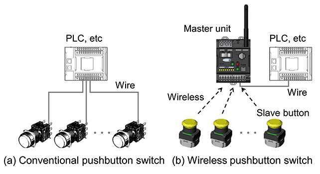
One of the common control devices used for wireless communication on the production line is a wireless pushbutton switch (wireless switch). The controlled system is wired to the pushbutton switch when the conventional pushbutton switch is used as shown in Fig. 1 (a), but when the wireless switch is used, wireless communication is established between the slave button (SB) that transmits the signal and the master unit (MU) that receives the signal as shown in Fig. 1 (b). Because the SB does not require a communication line and a power line, the person-hours required to modify the wiring for the production line layout change can be reduced. In addition, operation of the line becomes possible from a convenient place when the user carries the SB, which will make the new application possible. However, the problem of completely eliminating communication errors associated with wireless communication remains.
In the development of the wireless switch, the author defined the reliability of the wireless switch as the ability to allow operation exactly as the user wanted. The author carried out diversified studies in the aspects of the performance of the device and usability in order to improve reliability. This paper provides a description of the function that enables immediate notification of the wireless communication status to the user. In Section 2, the problems associated with wireless communication on the production line and the issues to be resolved to realize improvement in the reliability of the wireless switch are explained. Section 3 explains the outline of the communication status notification feature and three items of the technical issues to realize such a function. And finally, Section 4 provides the results of the experiment carried out in the actual manufacturing environment.
2. Challenges
2.1 Issues of wireless communication in manufacturing environment
Radio waves emitted from the wireless device generally propagate in the space affected by the phenomena like reflection and diffraction. The effect of such phenomena becomes complex as obstacles and noise increase, and communication failure becomes more likely due to fluctuations in radio wave intensity and RF interference. In the manufacturing environment where the space is generally enclosed by a building structure and filled with a number of obstacles, communication failures caused by the following phenomena need to be commonly considered3).
- • Diffraction produced by obstacles
- • Loss of intensity of propagating radio waves
- • Interference between direct waves and reflected waves (phasing)
- • Interference with radio waves emitted by other wireless devices or coming from the outside
- • RF noise emitted by the manufacturing equipment
These phenomena also affect the wireless switch, and it is quite difficult to completely eliminate communication failures in any manufacturing environment.
2.2 Issues associated with limited power generated
An issue peculiar to the wireless switch is the limited electrical power available. The slave button of the wireless switch is classified into those using a battery and into the self-generating type in which power is generated by operation of the switch, and the self-generating type requiring no replacement of the battery is becoming popular owing to the advanced energy harvesting technology4). Power generated by the self-generating type wireless switch in a single operation is quite limited, and it is difficult to equip the retry feature to automatically repeat transmission of the signal when communication fails. It is also a factor in reducing the reliability of the wireless switch.
2.3 Issues to be resolved to improve reliability
Issues explained in Subsections 2.1 and 2.2 are issues related to the reliability of communication, but these issues are difficult to resolve fundamentally based on the communication and power generation technologies at present. But the author considered the feature of the wireless switch urging the user to take appropriate action if communication fails will be able to make up such shortfalls in reliability.
For example, the communication success ratio can be improved if the user can notice that a communication failure has occurred and repeat the operation of the switch immediately when the first operation fails as an alternative means of a retry feature. Improvement of the communication success ratio can be also expected if the user can place the wireless switch in a position where a communication failure is less likely considering the phenomena explained in Subsection 2.1. Considering such a nature, the author considered an operation integrating the user and the wireless switch function, in other words, improvement of man-machine cooperation is an effective means of maximizing the reliability of communication. To realize such an operation, the following two items were selected as the targets to be resolved.
- • To assist user judgment whether the communication is successful or not
- • To assist in locating the switch in a position suitable for reliable communication
Detailed explanations of the above are provided in Subsections 2.4 and 2.5 respectively.
2.4 Improvement of discrimination between communication success and failure
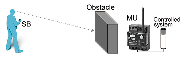
One of the factors in improving man-machine cooperation is to help the user make a judgment on communication success or failure. In the manufacturing environment where many obstacles exist, operation of the slave button may be made from the point where the controlled system cannot be seen directly as shown in Fig. 2. The following problems can occur in this case.
First, consider a case where a communication error occurred for some reason. In that case, a user needs to operate the slave button again recognizing that the communication failed. If the controlled system is not visible or if there is a time delay before the application responds, recognition of the communication error is difficult, and it will take time until the user retries the operation. The result is a production delay or limited applications in which the wireless switch can be practicably used.
Conversely, it is also possible that the user cannot recognize that the communication is successful. In such a case, the user may duplicate the operation of the SB even if the control is already started. For certain applications, measures to prevent malfunctioning of the system will be required that can occur when duplicated operation of the SB is made. As explained above, a feature discriminating success or failure of the communication is important for the wireless switch where a retry feature is provided by the operation of the user.
2.5 Easy to place the switch in a position suitable for reliable communication
Another issue is to make placement of the SB easy in a position suitable for reliable communication. Placement of the SB in a position where a certain level of radio wave intensity can be maintained even when attenuation and/or interference of the radio wave takes place in propagation is effective. It is not easy for the user without expert knowledge in wireless communication. If the SB is placed in a position where the radio wave attenuates significantly because of many obstacles, communication errors will frequently occur and reliability will be low. Conversely, if strict restrictions to place the SB close to the master unit are applied, flexibility in using the wireless switch will decrease, although the communication success ratio improves because of the reduced radio wave attenuation. Communication tests need to be repeated for different positions of the wireless switch during installation, and additionally fine adjustment may be needed after installation so that the switch can be placed in the best position. As explained above, the user needs to exert much effort in the selection of the position where the conventional type of wireless switch is used. The advantage of the wireless switch in reducing the person-hours needed for wiring work is also lost if the time required to determine the position of the switch becomes longer.
3. Development of Signal Reception Notification Function
3.1 Outline of signal reception notification function
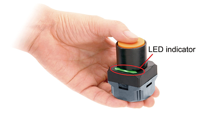
Two issues described in Subsections 2.4 and 2.5 can be resolved if (1) recognition of communication success or failure is possible wherever the SB is located and for any type of controlled system, and (2) determination is possible whether adequate radio wave intensity is available for communication. Accordingly, the author developed the signal reception notification function that notifies the user whether the communication is successful using the LED indicator on the SB. Fig. 3 shows the SB with the LED indicator and Fig. 4 shows the schematics as to how the system works.
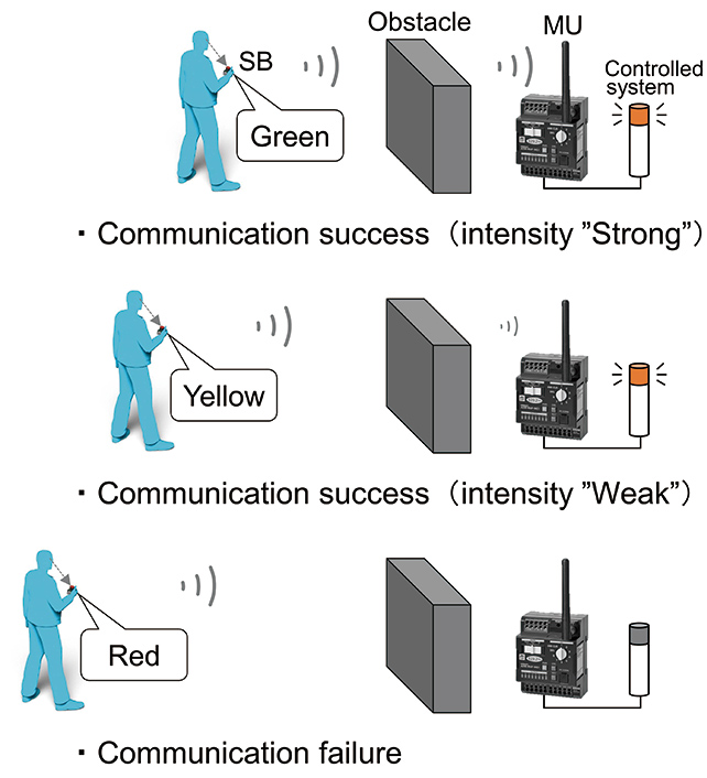
When the user operates the SB, the wireless signal is transmitted, and the LED indicator on the SB illuminates after transmission. The LED illuminates in three colors, and when the communication is successful and adequate radio wave intensity exists, it illuminates in green, when the communication is successful but the radio wave intensity is not adequate, it illuminates in yellow, and when the communication fails, it illuminates in red. The user can immediately recognize whether the communication is successful or not operating the SB watching the LED indicator even when the controlled object cannot be seen. When the communication is not successful and the red LED illuminates, the user can immediately retry operation of the SB. In selecting the position of the wireless switch, the position where a high communication success ratio is established can be selected without losing flexibility in the layout design by operating the SB several times from the area where green LED illuminates.
As explained above, the signal reception notification function can substantially improve the man-machine cooperation between the user and wireless switch and the reliability. This feature is very unique as such a feature is realized for the selfgenerating type wireless switch in which available power is quite limited. To realize the signal reception notification function, several new technologies and techniques are required. Principal items to be studied and the outline of such items are shown in Table 1. The details of these items are described in subsections 3.2 through 3.4 respectively.
| Technology/Technique | Outline |
|---|---|
| Two-way communication processing flow | Invention of the method to return transmission condition to the SB and to determine the color of the LED indicated. |
| Determination of the threshold of radio wave intensity | To determine threshold level of radio wave intensity when illumination of the green LED or yellow LED is selected |
| Ensuring amount of power generated | Method to ensure the power required for operation of the two-way communication processing flow |
3.2 Two-way communication processing flow
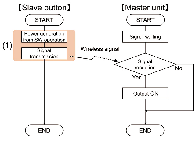
The processing flow for the conventional wireless switch is shown in Fig. 5. This one-way communication processing flow is where the wireless signal is transmitted to the MU when the SB is operated and the MU, upon receipt of the signal, sends the control output.
On the other hand, Fig. 6 shows the processing flow developed by the author to realize the signal reception notification function explained in Subsection 3.1. This processing flow is a two-way, three stage system consisting of the communication path from the SB to MU and also from the MU to SB and LED control5),6)
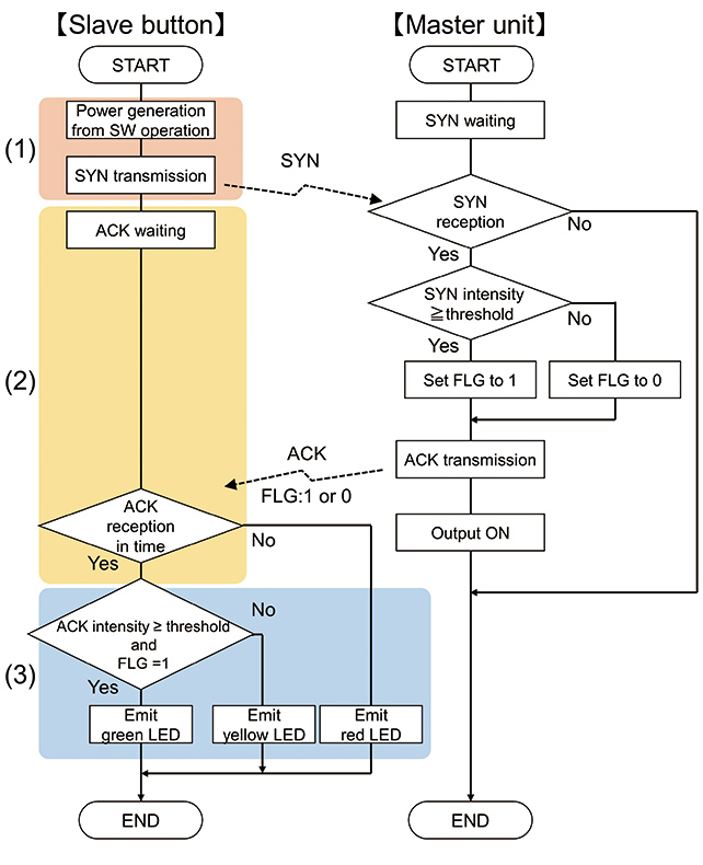
When the user operates the SB, power is generated in the SB and transmits a signal (SYN) to the MU. When SYN is sent, the SB changes its status of waiting for the response from the MU. The MU when receiving the SYN determines whether the radio wave intensity of SYN is above a certain threshold or not. Then the MU generates the control signal and transmits the receipt acknowledge signal (ACK) to the SB. The ACK contains the information on the result of the judgment about the radio wave intensity of SYN (FLG). The SB determines the radio wave intensity of the ACK received, and the green LED illuminates when the intensity of both the ACK and SYN is above the threshold, and the yellow LED illuminates when it is not so. When the MU cannot receive the SYN from the SB, ACK is not sent. When a certain period of time passes in the status of waiting for the response, the SB determines that the communication failed and the red LED illuminates.
This processing flow makes the determination of communication success or failure and the radio wave intensity possible by exchanging the minimum quantity of data. So the communication protocol can be simplified and functioning with the minimum time delay, and low power consumption can be realized. As explained later in Subsection 3.4, the feature of low power consumption is very critical for installation of the notification feature in the SB with limited power.
3.3 Determination of the threshold of radio wave intensity
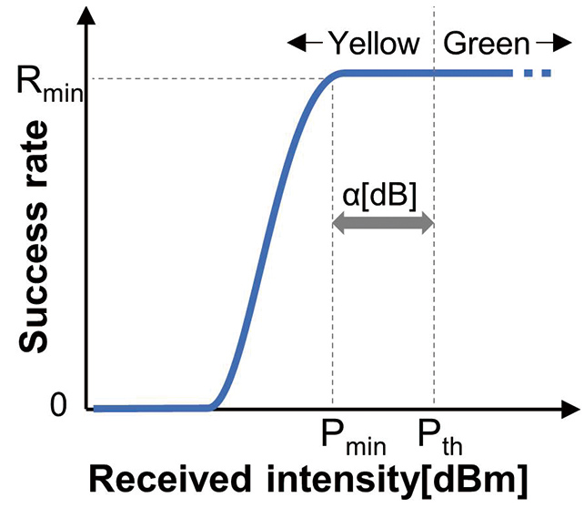
Using the two-way communication processing flow explained earlier, notification whether the radio wave intensity of the signal received is above or below the threshold becomes possible. So that this notification can be used as a criterion to determine whether communication condition is good or poor, it is important at which level the threshold ( [dBm]) should be determined. If fluctuation of the radio wave intensity received by the MU is extremely small, the communication success ratio of the MU shows the trend as shown in Fig. 7. Where
  is the communication success ratio required as the specification of the product and
  [dBm] is the minimum value of radio wave intensity required to maintain .
On the actual production line, the radio wave intensity of the signal received by the MU constantly fluctuates because of the effect of obstacles existing in the area. Accordingly, should be determined according to the following equation taking into consideration the typical radio wave intensity fluctuation level  [dB] (in particular to the direction of attenuation) produced at the factory.

should be determined based on the results of past studies. Fluctuation of the radio wave intensity in the manufacturing line can be expressed by the following Nakagami-Rice distribution  according to the results of the experiment in7).


-
 : Radio wave intensity of the steady-state component
-
 : Radio wave intensity of the fluctuating component
-
 : Modified Bessel function of the first kind of order zero
-
 : Radio wave intensity of the signal received by MU
 is the parameter corresponding to the ratio of the steadystate component to the fluctuating component, and as becomes smaller, the fluctuation in the radio wave intensity increases. Fig. 8 shows the distribution function for the respective values of .
  is an average of the changing field intensity of radio wave received.
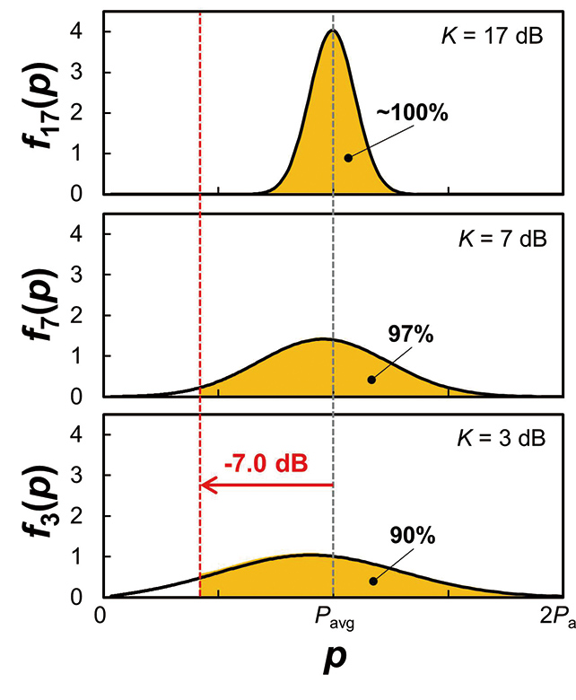
Fig. 8 indicates that level of the radio wave intensity fluctuation of the signal received by the MU changes significantly by the value of K, in other words, by movement of the equipment made of metal and the operators. In determining the value of , the value of must be large so that any fluctuation in the severest condition (= 3 dB) can be fully covered. But in such a setting, the yellow LED will frequently illuminate even in a condition where the communication success ratio is high, which will make the system hard to use in practical application. So the author decided to use = 7 dB so that 90% of the radio wave intensity fluctuation could be covered when = 3 dB, and determined as expressed by the following equation.

3.4 Ensuring the amount of power generated
Processing of (2) and (3) of Fig. 6 in the processing flows explained in Subsection 3.2 becomes necessary because of the addition of the signal reception notification function. The power required for these features needs to be provided by the power generated by the SB. Fig. 9 shows the minimum required power for the processing of these features obtained by the experiment. Power consumption when the LED indicator illuminates in green, yellow, and red was designated as  ,
,  , and
, and  , respectively, and measurements were made in three stages (1),(2), and (3) in Fig. 6.
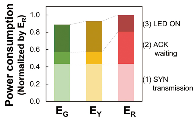
The graph indicates that the power consumption increases about twice due to the addition of the processing in (2) and (3) when compared with the value for the conventional wireless switch in (1) only. The reason why is the largest among , , and is that the condition in (2) must be maintained until the timeout when the red LED illuminates. In order to effectuate the two-way communication processing flow, power generated by the SB must be larger than . The SB contains the power generation module that produces power by electromagnetic induction. The generated power depends on the velocity at which the module is pressed, and the required power cannot be obtained by the simple mechanism where the operating mechanism moves the power generation module at the same time. To increase the power generated, the velocity of the operation must be increased by a certain internal mechanism. So the trigger action mechanism as shown in Fig. 10 was invented using the technique used in emergency stop button5),6).
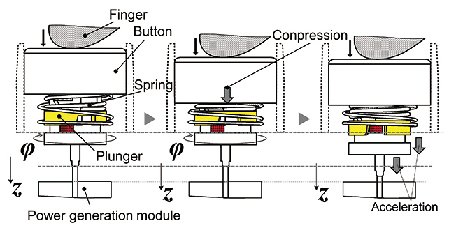
In the trigger action, the actuation of the button in the z-direction is converted into movement along the  -direction. When the user presses the button in the z-direction, the plunger rotates in the -direction along the slot provided internally. When the plunger rotates to a certain angle, energy stored by the spring is released, and the plunger pops out in the z-direction. The velocity of the plunger popping out is dependent on the spring constant and remains almost the same independent of the velocity when the SB is pressed.
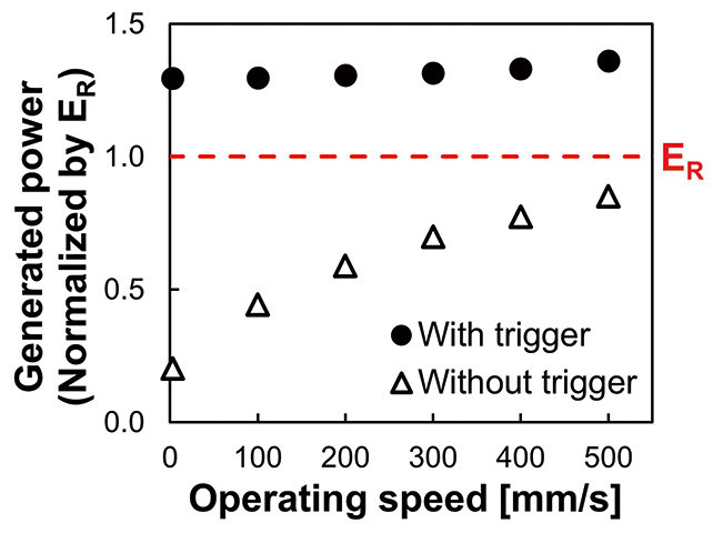
Fig. 11 shows the results of the measurement of the difference in the power generated and caused by the presence of the trigger mechanism. The abscissa is the velocity when the button is pressed and the ordinate is the power generated and normalized by . When the ordinate value exceeds 1, the required power is generated. When no trigger action is used, the power generated changes according to the velocity of the button operated, but it does not attain the required in any case. On the contrary, when the trigger mechanism is used, the power generated increases substantially, which exceeds independent of the velocity of the operation. Incorporation of the trigger action mechanism makes it possible to provide the power required for the signal reception notification function regardless of the method when the button is pressed. This makes both the benefit of no battery replacement of the self-generating system and improvement of reliability by the signal reception notification feature possible.
4. Verification Results in the Actual Production Line
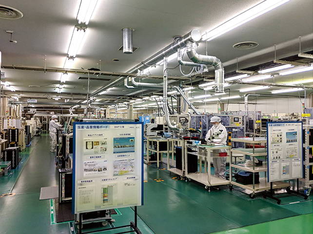
This section provides the verification results of the signal reception notification function on the actual production line in operation. Fig. 12 shows the layout of the factory used in the experiment, and Fig. 13 shows the interior view of the factory. A number of mounting lines of electronic devices and assembly lines are located in the factory, and the height of the production equipment and shelves is approximately 1 to 2 meters. As the automatic product assembly machines are constantly operating and the operators are frequently moving, a wireless communication environment is likely to fluctuate.
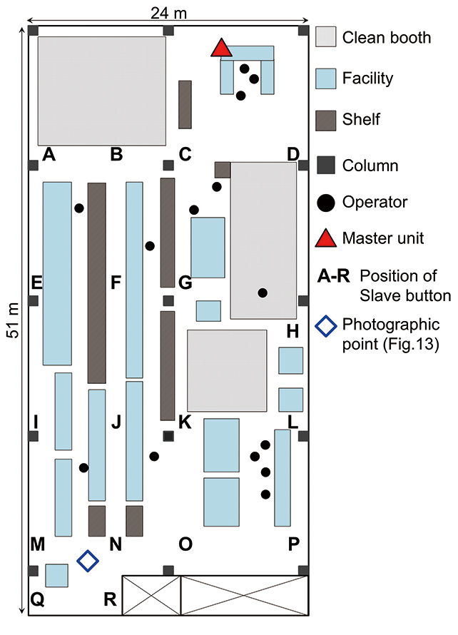
In the test, the MU was placed at the point shown in Fig. 12, and the ratio of the LED colors that illuminated when the SB was operated 20 times at each point from A to R, respectively, was recorded. Table 2 shows the test conditions, and Fig. 14 shows the test results.
| Center Frequency | 929.2 MHz |
|---|---|
| Communication Method | GFSK simplex communication |
| Transmission Power | 0 dBm max. |
| Master Unit Antenna Gain | 2 dBi |
| Installation Height of Master Unit | 1.2 m approx. |
| Installation Height of Slave Button | 1.2 m approx. |
| Operation of Slave Button | Manual (Operation Interval. 1 s approx.) |
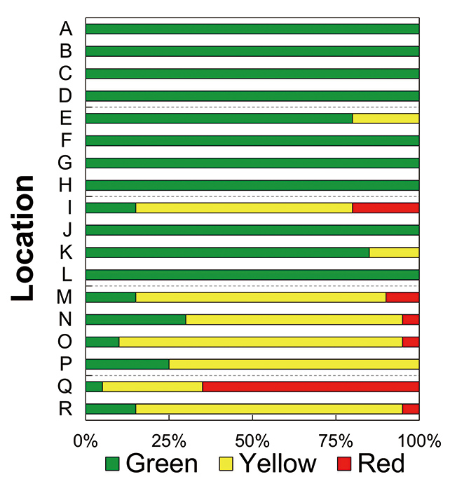
The positions of the SB where the MU is directly in the line of sight are C, D, F, and G but only where obstacles were relatively rare. Accordingly, it is difficult to visually confirm whether the communication is successful when operation of the SB is made at positions other than the above four points when the conventional wireless switch without the signal reception notification feature is used. Particularly, the communication success ratio at positions I, M, N, O, Q, and R is less than 100%, and it is likely that a certain time period is required until the user retries the operation. Conversely, when the SB with the signal reception notification feature is used, whether communication is successful can be immediately recognized from any of the positions from A through R. Accordingly, the operator can retry operation of the SB when the communication is not successful without losing time.
In addition, in determining the position to place the SB of the wireless switch, a high communication success ratio can be consistently expected even when there is a radio wave intensity fluctuation caused by the environment if the position is selected from positions A through D, F through H, J, and L where the green LED constantly illuminates. While at position P, although the communication success ratio is 100%, but the large proportion is in yellow LED, which indicates that tolerance for fluctuations in the radio wave intensity is small. So, it is desirable to avoid position P when it is necessary to reduce the number of occasions where retrial of the operation needs to be reduced. As explained above, the user can easily recognize whether the communication is successful or not at different positions of the SB and can select the position of the SB depending on the communication success ratio required for specific application.
The results of this verification test indicate that two issues selected in Subsection 2.3, in other words, “difficulty in judgment whether the communication is successful” and “difficulty in locating the position suitable for reliable communication” are clearly improved. The author considers that the reliability of the system is significantly improved from the improved man-machine cooperation between the operator and the wireless switch.
5. Conclusion
This paper describes the outline of the signal reception notification function and the issues to be resolved for improved reliability of the wireless switch, which improves man-machine cooperation with the user, and the test results conducted in the actual manufacturing environment. In addition to what is explained in this paper, the wireless switch developed by the author also considers the maximized reliability of the communication by enhancement of the fundamental performance of the device. The author intends to develop the wireless switch that is more reliable and more flexible to use in acquiring knowledge about how the wireless devices are used in diversified environments. To make wireless operation of other control devices other than the wireless switch possible, the author also intends to conduct research to realize more flexible production lines.
To conclude, the authors express special gratitude to the persons who extended assistance in the development of the method and in making this paper possible.
References
- 1)
- Technology Strategy Committee (No. 14), Telecommunications Technology Sub-Council, Telecommunications Council. Promotion of Narrow-space Wireless Projects the Ministry of Internal Affairs and Communications (2017-02-27) (in Japanese). http://www.soumu.go.jp/main_sosiki/joho_tsusin/policyreports/joho_tsusin/gijutsusenryaku/02tsushin03_04000245.html, (accessed 2019-01-11).
- 2)
- Nalin, M. Industrial Ethernet is now bigger than fieldbuses. HMS Industrial Networks. 2018-02-27. https://www.hms-networks.com/press/2018/02/27/industrial-ethernet-is-now-bigger-than-fieldbuses, (accessed 2018-12-12).
- 3)
- Itaya, S. Towards realization of the smart-factory using wireless communication technology. Journal of the National Institute of Information and Communication Technology. 2017, Vol.63, No.2, pp.35-39 (in Japanese).
- 4)
- Mitcheson, P. D. et al. Energy Harvesting From Human and Machine Motion for Wireless Electronic Devices. Proceedings of the IEEE. 2008, Vol.96, No.9, pp.1457-1486.
- 5)
- OMRON Corporation. Wireless Switch. U.S. Patent 2018/0158626A1, 2018-06-07
- 6)
- OMRON Corporation. Power Generation Apparatus And Wireless Switch. U.S. Patent 2018/0156632A1, 2018-6-7.
- 7)
- Ozawa, H.; Fujimoto, T.; Katayama, M. Measurement and Modelling of Propagation Characteristics of Electromagnetic Wave for Realization of Highly Reliable Control Wireless System (in Japanese). IEICE Technical Report. 2015, Vol.115, No.366, pp.191-196.
The names of products in the text may be trademarks of each company.