


Realization of Thin Push Button with Large Transparent Section Structure
- Mechanical components development
- Thin structure
- Transparent structure
- High durability
- Impact resistance
In the casino industry, which is a tourism industry that provides entertainment and leisure time creation and amusement for people, the direction for attracting players to casino machines has been evolving rapidly in recent years, and the visual area has been expanding year by year. However, the SPIN button, which is an important button for starting a game, remains a conventional physical push button because it needs to feel realistic. We have realized a physical push button that is thin enough to be installed on the liquid crystal display (LCD), yet provides a realistic push feeling, better switch durability than conventional buttons, and a water resistance function to provide a SPIN button for a new generation casino machine for the casino machine industry by combining technologies that have been accumulated in the Japanese amusement industry. This SPIN button allows casino machine manufacturers to easily change the display of the button surface using an LCD installed underneath the button for each gaming action. In addition, it is possible to create continuous LCD performance with the LCD display on the outside of the push button switch, which is a step toward realization of a futuristic casino machine.
1. Introduction
Nowadays, we can frequently see a device capable of displaying and operation by combining an LCD and a touch panel like a ticket vending machine in a railroad station and an ATM as a natural phenomenon. Although the casino machine (slot machine) was a device combining a mechanical reel and a physical push button in the past, the feature has greatly changed in recent years. Furthermore, the reel is a cylindrical part that rotates in the casino machine and displays printed patterns and numerals, and pushing a SPIN button by a player rotates it and pushing it again stops it. The arrangement of patterns and numerals on the reel when it stops naturally determines the amount of money won by the player. Such a mechanical reel was replaced with a large LCD, and the motion of the reel is expressed by the LCD. In addition, the operation button has the construction of the combination of the LCD and the touch panel instead of a conventional physical push button. Fig. 1 shows the schematic diagrams of casino machines of the machine reel type and the large LCD reel type.
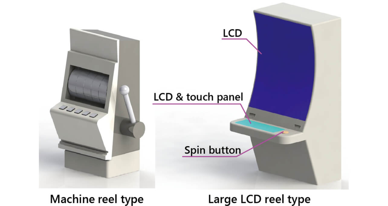
In addition, Fig. 2 shows the schematic comparison diagrams viewing from the top of each type.
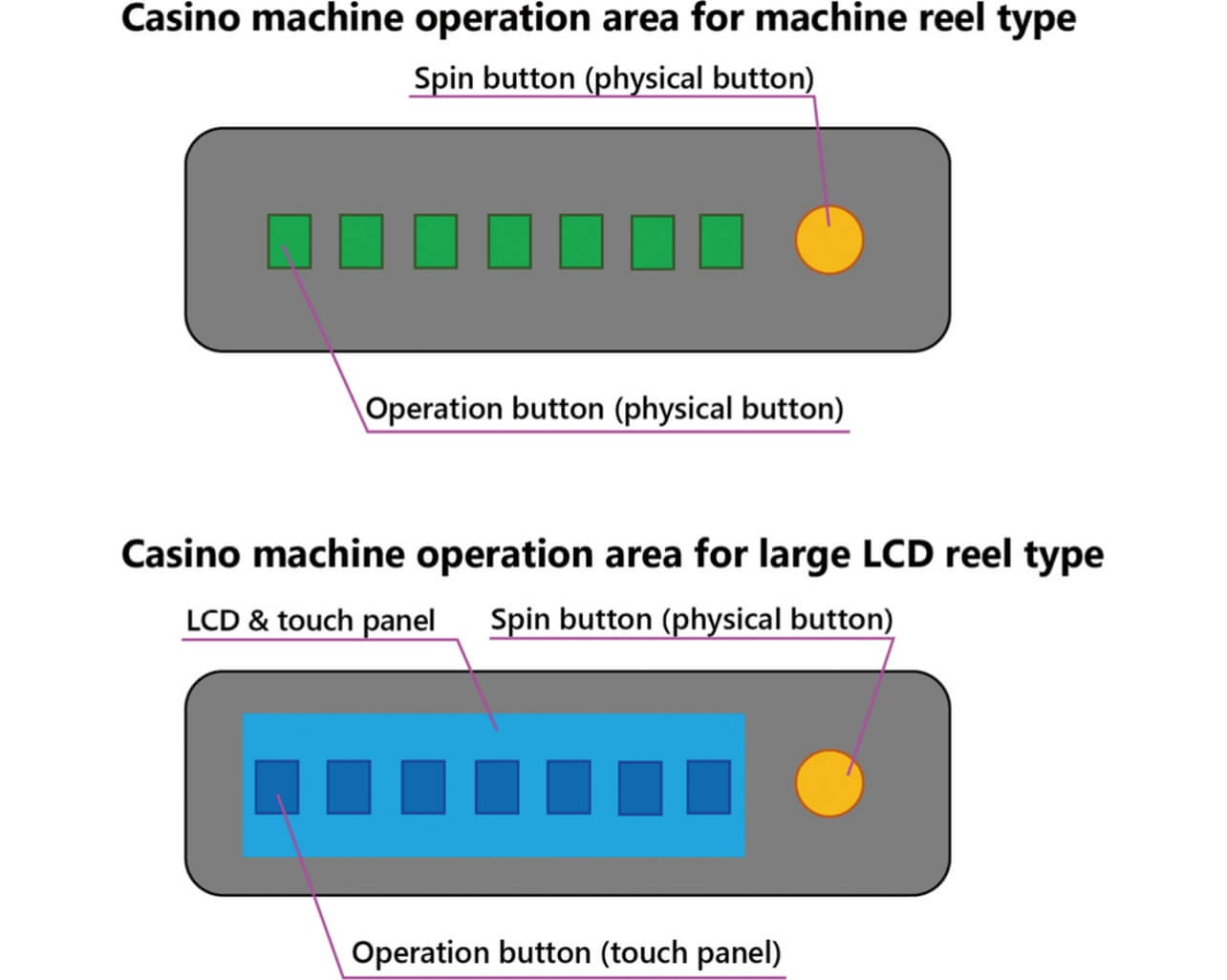
The reason why the casino machine and the operating button changed as above is that the improvement in the sense of immersion by a player and the improvement in the working rate of the casino machine were the objectives. The LCD installed in each part of the casino machine enlarges the direction region and contributes to the improvement in the sense of immersion by a player.
Notwithstanding such a trend of the casino machine industry, the operation for starting a game (operation for starting the rotation of the reel) is implemented by pushing a physical button, the SPIN button, prepared separately from the touch panel. Pushing the SPIN button means spending money to start a game. Therefore, the SPIN button still exists as a physical button with an operational feel in order to prevent a player from pushing unintentionally.
In addition, many conventional SPIN buttons are push buttons with an operational feel in the structure facilitating installation in a casino machine. This is to enable replacement once a SPIN button is broken. Fig. 3 shows the schematic sectional diagram of the conventional SPIN button.
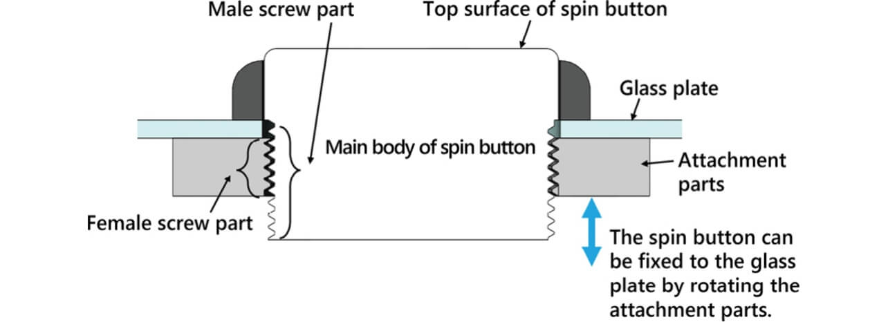
Providing male threads and female threads to the main body of the SPIN button and the part for installing the button, respectively, and the rotation of the part for installing the button allows attachment of the SPIN button to the glass plate surface. This enables complete attachment and detachment work for the SPIN button without using a tool such as a screwdriver.
Since the SPIN button has the feature of immediate replacement if broken, the SPIN button itself has a simple and cost-reduced structure. Although casino machines are in the mainstream of adopting large LCDs and operation by touch panel showing the evolution with a future feeling, the SPIN buttons are outside of this trend.
Table 1 shows the summary of advantages and disadvantages of the conventional SPIN button.
| Advantage | Disadvantage |
|---|---|
| Unit price of product is cheap | Appearance of product has no sense of high quality |
| Excellent in exchangeability | Durability of switch operation is low/having no water-resistant function |
| Sense of switch operation with a good feeling because of microswitch adoption | Poor displaying function (narrow region and limited contents) |
As afore-mentioned, the creation and focus has been on the cost, for example, the top of the SPIN button has been designed with the technique to print on the surface of the button top part and to insert a printing sheet to the back of the button top part. Although this construction can reduce the product cost, conversely, there is the disadvantage that replacements of the button top part and the printing sheet are required when a design change is desired.
We have realized a SPIN button with a sense of high quality and with a thin and transparent structure capable of displaying various pattern designs on the top of the SPIN button by utilizing the LCD shown in Fig. 2 toward the realization of a casino machine with a future feeling by incorporating various technologies, such as a shock resistant structure and decorative illumination function, which we have accumulated in the Japanese amusement industries for SPIN buttons that are outside the trend of casino machines in recent years.
2. Needs in casino machine industry
Although the trend of casino machines is in the combination of an LCD and physical SPIN button, we have grasped that the problem of how we can attract players always exists. In order to solve this problem, each casino machine manufacturer is going to be particular about the direction as described in chapter 1, and, for example, the LCD display region of the operation panel is enlarged, and images more attractive to players are displayed.
If the operation button is of the touch panel type, the LCD display region can be enlarged by arranging a sheet-like touch sensor between the glass plate and the LCD. However, since the SPIN button, a physical push button, has the thickness of a button, the LCD cannot be arranged underneath the button. In order to enable the easy change of the design of the top of the SPIN button using an LCD as a method for attracting players, two plans can be considered—(Plan 1) the LCD is placed above the SPIN button and (Plan 2) the SPIN button is made thinner with a transparent structure—and the LCD is placed under the thinner SPIN button. Fig. 4 shows the schematic diagrams of Plan 1 and Plan 2.
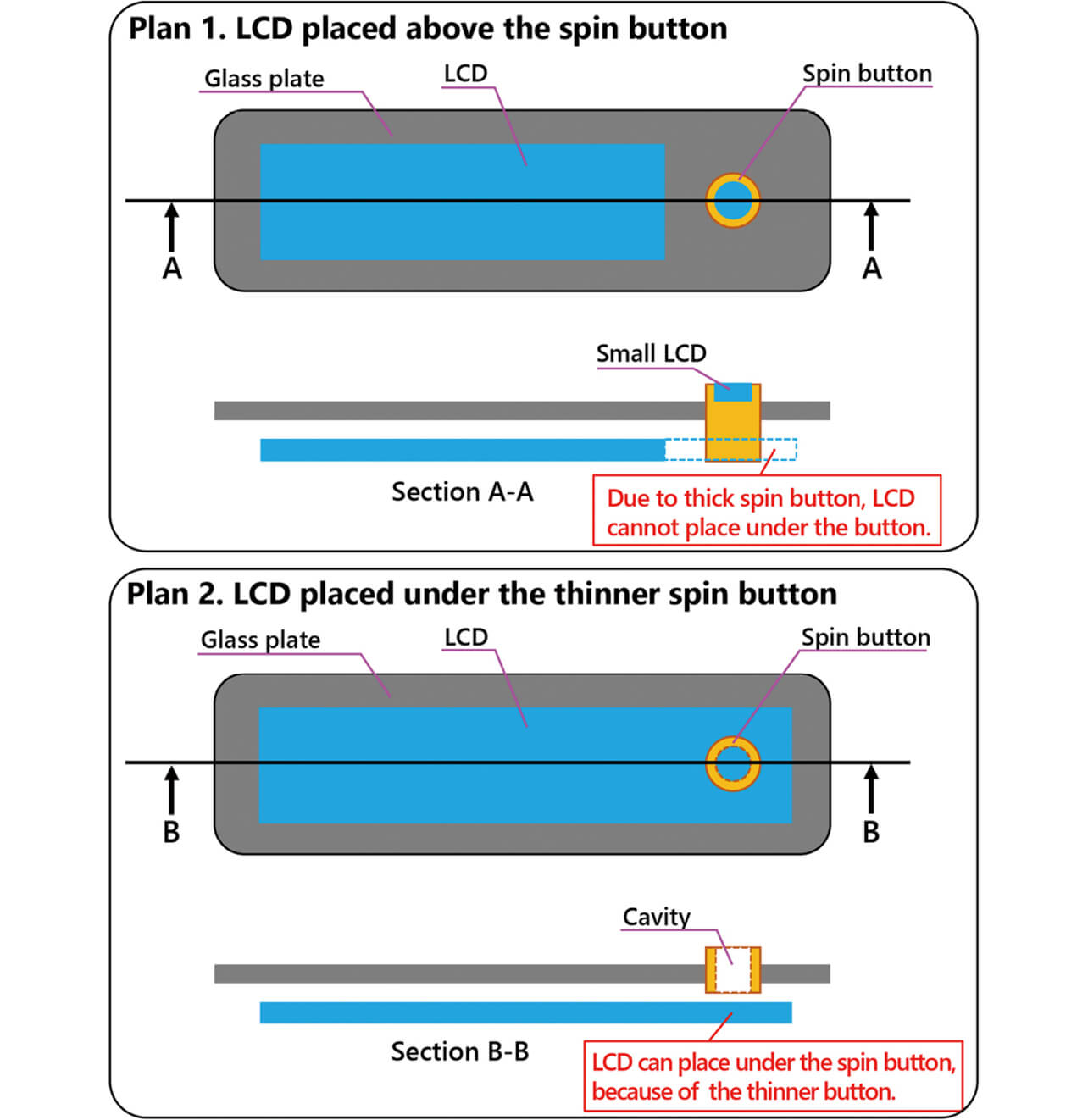
(Plan 1 and Plan 2)
Plan 1 has the disadvantage that the cost for a small LCD accommodated in the button is added, and display control needs to be created for the button. On the other hand, Plan 2 does not require the loading of an LCD on the button itself, the display control can be performed by extending the operation panel LCD, and control only for the button is not necessary. In addition, since Plan 2 shares the LCD for the operation panel and the SPIN button, the LCD can be displayed from the outside of the external form of the SPIN button directly, and continuity can be provided to the displays of the operation panel and the SPIN button. Fig. 5 shows the concept for proposing the future casino machines based on Plan 2.
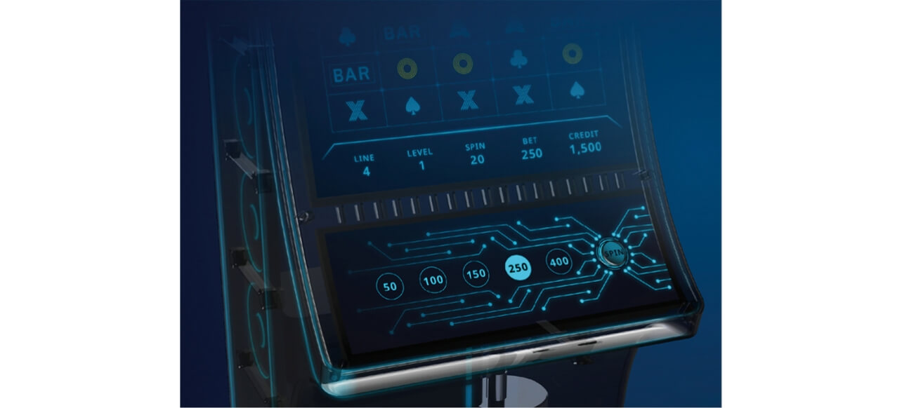
The realization of the operation deck with a high direction property is possible by providing continuity to the internal and external LCD displays of the SPIN button.
As mentioned above, the Plan 2 is more effective for enlarging the LCD display region. However, since the SPIN button structure of the Plan 2 requires thinning and transparency of an LCD display underneath the button, the space for accommodating the switch function is small. In spite of such restriction, it is necessary to maintain or improve the basic function as the SPIN button. Table 2 shows the list of basic functions of the SPIN button.
| Function | Market demand |
|---|---|
| Durability of switch operation | No destruction in the condition of 4 million times or more at 30 N |
| Shock resistance | No destruction in the condition of 1 million times or more at 300 N |
| Static electricity resistance | No destruction in the condition of contact discharge of ±10 kV and aerial discharge of ±27 kV |
| Attachment/detachment performance | Capable of attaching/detaching SPIN button without tools |
The items of market demand shown in Table 2 are based on the information obtained by our proposal activities and business talks with each casino manufacturer.
In addition, it is necessary not only to incorporate the basic functions of the SPIN button into a small space but also to adopt a design that brings about a sense of high quality. Narrowing the bezel of the SPIN button as much as possible and selecting materials with a shiny appearance for the bezel part can be proposed as the method for this. Furthermore, enabling the arrangement of the SPIN button on the LCD as shown in Plan 2 of Fig. 4 is required to bring about a feeling for the future as a more detailed proposal.
3. Technical problems
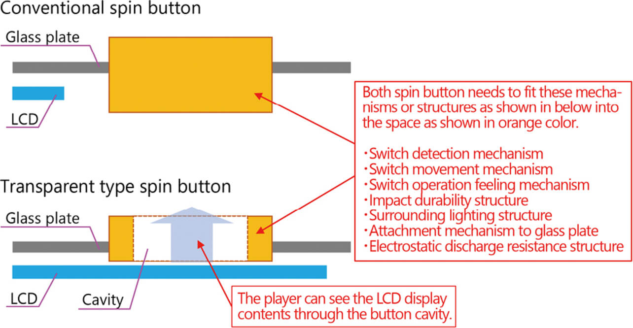
As mentioned in chapter 2, in order to realize a SPIN button with a transparent structure capable of transmitting through the LCD display (hereafter referred to as “SPIN button of LCD display and transparent type”) shown in Plan 2 in Fig. 4, it is necessary to adopt a structure that functions as a conventional switch in a limited space and to provide an appearance as excellent in design. Fig. 6 shows the comparison of the cross-sections of the conventional and transparent type structures of the SPIN button. Hereafter, we will describe the problems for accommodating various mechanisms and structures in a limited space.
3.1 Problems for structures related to switch function
The size of a conventional SPIN button is often 70 mm to 90 mm in diameter to enable visual recognition of the pattern design on the top of the button and to match the size of the hand of a player who operates the button, and the height of the button is about 80 mm. A microswitch1) is arranged underneath the button, and the sliding action of the SPIN button is performed over the microswitch. In addition, the product cost of the SPIN button can be reduced by utilizing the microswitch for input detection (on/off detection) by the SPIN button.
However, the adoption of this microswitch to realize the SPIN button of the LCD display and transparent type is very difficult for the following reason. The first is the problem of size. In the case of the button structure shown in Plan 2 of Fig. 4, since the height of the button must be about 15 mm, the microswitch occupies a large space because its height is about 7 mm even in a small size. In addition, since the SPIN button of the LCD display and transparent type cannot have a sliding structure in the middle of the button like a conventional button, the button is tilted if the end of the button is pushed. In order to enable input detection by the microswitch even when the button is tilted, the arrangement of multiple microswitches is required. The arrangement of multiple microswitches is not realistic because more space is occupied. Furthermore, there is also a problem that the use of multiple microswitches raises the product cost.
The shock resistant performance of a microswitch in such a small size is low because the stroke necessary for on/off detection of a switch is short, and the structural stoppage of the stroke before the application of a large load on the microswitch is difficult. In addition, since the durability of switch operation of a single microswitch is also low, the market demand for the basic performance shown in Table 2 cannot be satisfied.
As mentioned above, the realization of the SPIN button of the LCD display and transparent type requires a switch detection mechanism other than a microswitch. The switch detection mechanism must be thin and offer excellent durability and shock resistance.
3.2 Problem of structure related to water resistance function
Although conventional SPIN buttons with a water resistance function are rare, when the button is damaged by food or beverage, the action of the replacement with a new one has been taken since players enjoy the game in a casino hall while eating or drinking. The prevention of liquid from entering the SPIN button and the operation panel from the upper part of the button is demanded as a function by the market because the replacement work raises the cost, although the button itself is cheap. A physical push button has a zone where the moving part and the fixed part slide with each other, and this zone is provided with a clearance. Since liquid can easily enter inside the SPIN button through this clearance, the elimination of this clearance is necessary. One of methods for eliminating this clearance without disabling the sliding action between the moving part and the fixed part is to connect both parts with an elastic member.
However, no damage to the elastic member for the connection must occur from the repetitive operation of the switch. The increase in the thickness of the elastic member to avoid damage tends to make switch operation heavy because the rigidity of the elastic member is higher. In order to solve this trade-off, the control of the shape and thickness of the elastic member is considered necessary. In addition, how to install the elastic member in a narrow space is also a problem as afore-mentioned in section 3.1.
3.3 Problem of structure related to securing static electricity resistance
Casino machines are often installed on a carpeted floor in a dry, well air-conditioned environment, such as in a hotel. Therefore, it is important to provide resistance to strong static electricity. Generally, the entry of static electricity inside the SPIN button is prevented by providing creepage distance between the top of the SPIN button and the electrical board inside that button. The guideline for setting creepage distance is 1 mm per kilovolt of aerial discharge. The aerial discharge of 27 kV requires creepage distance of about 30 mm according to Table 2. As afore-mentioned in section 3.1, since the height of a conventional SPIN button is about 80 mm, creepage distance of about 30 mm can be secured. However, since the height of the SPIN button of an LCD display and transparent type must be about 15 mm, creepage distance of about 30 mm cannot be secured.
As mentioned above, how to secure static electricity resistance in the condition of sufficient creepage distance is difficult and is a problem.
3.4 Problem of product appearance
As mentioned in chapter 2, the SPIN buttons require a product appearance that makes users feel it is high quality and part of a future. In recent years, bezel-less products loaded with LCDs, such as smartphones and laptop personal computers, have increased. Although the main purposes are weight reduction, size reduction, and enlargement of the display area, the modification provides the feeling of high quality and future because the design is changed to a sophisticated one due to the removal of ineffectual parts. According to this, it is necessary to incorporate the structures described in sections 3.1 to 3.3 so as to aim to allow the SPIN button of the LCD display and transparent type to be bezel-less as much as possible and so as to make the LCD display region as large as possible.
In addition, the height of the LCD display section of the SPIN button has a problem. Since the LCD is arranged in a position lower than the SPIN button, when a large distance exists between the top of the SPIN button and the LCD, there is a possibility of generating the feeling that something is wrong because the display of the SPIN button seems to be sunk from the top of the button. Therefore, a device for making the LCD display come up to the top of the button is required.
Other than the above, the element for producing the sense of high quality is decorative illumination. A more modest color and a more even luminescence produce a greater sense of high quality. In addition, the decorative illumination not only provides the sense of high quality but also attracts the eyes of people other than the player, giving a new player the opportunity to start. However, it is necessary to provide the light-emitting part in a limited space, make that light emission uniform, and prevent the light emission from disturbing the LCD display in the middle of the SPIN button.
Furthermore, the input/output signal for detecting the switch on/off status and the electric power for decorative illumination of the SPIN button are supplied to the SPIN button through a harness connected to the casino machine. When the SPIN button is arranged on an LCD, since this harness is laid between the glass plate and the LCD, the player considers it ugly. Since the harness is essential, the device to make its presence not noticeable is required.
4. Technical content
In order to realize the SPIN button of an LCD display and transparent type, we will explain the solution for each problem described in chapter 3 below:
4.1 Realization of structure related to switch function
Here, the problems were the selection of a thin-type system capable of detecting the switch on/off status, suitable action to the operation of switch-end pushing, and measures for load resistance.
First, we will describe the switch detection system and the suitable action for the operation of end pushing. There are many switch detection systems, such as the method for detecting on/off status by shielding/flooding light axis using a photo sensor, the method for detecting on/off status by adjusting voltage high/low using a dome contact, and the method for detecting on/off status by adjusting pressure higher/lower than the threshold value using a pressure sensor. Among these systems, the dome contact and pressure sensor systems allow creating a thin sheet-like device. Furthermore, among these two systems, the pressure sensor using the piezo resistance effect owns the highly durability for repetitive switch operation. Thus, the pressure sensor system was adopted as the switch detection system in this product. Fig. 7 shows the top view of the pressure sensor used for this product.
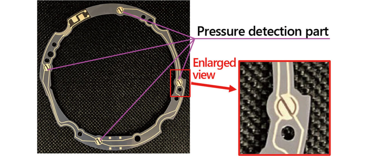
It was described that the external shape of this product is circular, and the external shape of the pressure sensor is of the ring type. This film-like pressure sensor is 0.2 mm thick, and multiple pressure detection parts can be provided. As shown in Fig. 7, the pressure sensor is provided with four pressure detection parts so that even if the button is end-pushed, one or more among four receives pressure. Moreover, a parallel circuit is formed for these four pressure detection parts so that the product can transmit a switch signal even if only one part is applied with pressure.
Then we will describe the content of measures for load resistance. First, since the withstanding load of the pressure detection part is 50 N, the structure to make the load to pressure detection part less than 50 N even if this product is strongly pushed in was required. The mechanism capable of structurally receiving excessive load by a stopper was adopted. Fig. 8 shows the detailed cross-section of the section where the pressure sensor is pushed down.
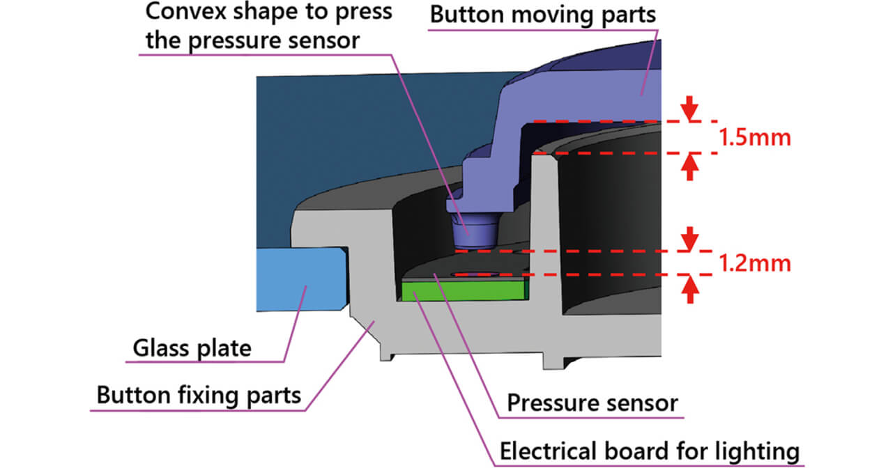
The downward movement of the button moving parts allows its convex shape to contact the pressure sensor to transmit a switch signal. The distance from the start of the button moving parts to the contact of the parts with the pressure sensor was set at 1.2 mm in reference to the stroke of the SPIN button. On the other hand, the distance of 1.5 mm until the contact of the button moving parts with the button fixing parts was provided. The purpose is to make the pushdown of the button moving parts always give a load to the pressure sensor considering the variation in assembly accuracy. That is to say, the pushdown of the button moving parts down to the lowest point generates interference of 0.3 mm between the parts and the pressure sensor. Therefore, the button moving parts was made of an elastic material so that the load was less than 50 N even if the parts was compressed by 0.3 mm. Since the material is related to the water resistance function, we will describe it later in section 4.2.
Then, we will describe the withstanding load performance. Fig. 9 shows the detailed cross-section in the condition where the button is pushed down by the button moving parts.
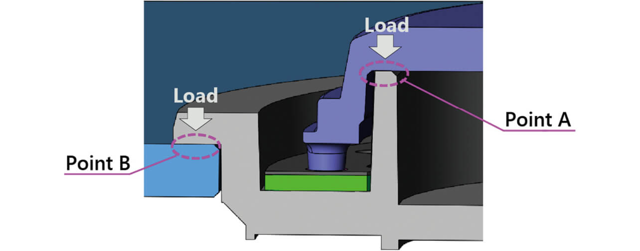
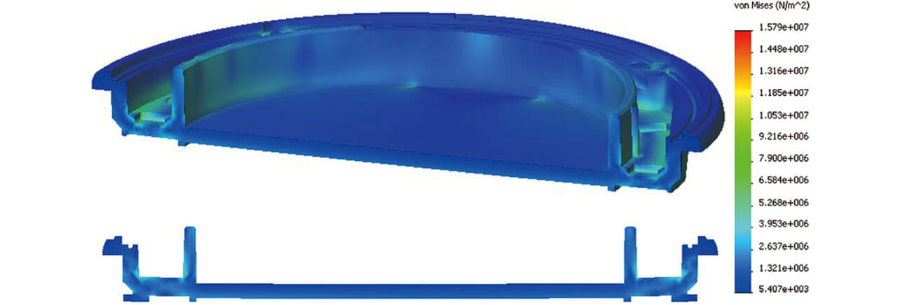
As shown in Fig. 9, the button fixing parts receive the load at point A from the button moving parts. And, the received load is structurally supported at point B where the button fixing parts contact the glass plate. Therefore, the selection of a material for the button fixing parts and the thickness are important. Polycarbonate with high shock resistance was selected as the material, and the thickness required for each location was determined by stress analysis and experiments as shown in Fig. 10. As a result, the thickness of the peripheral wall and the bottom was set at 2.2 mm or more.
4.2 Realization of structure related to water resistance function
Here the problems were to provide a water-resistant structure in a limited place and to make the structure resistant to the repetitive action of switch operation. First, we will describe the water-resistant structure.
As mentioned in section 4.1, since the pusher of the pressure sensor required an elastic member, we studied whether the shape playing the role of a gasket for water resistance by extending this could be created. However, it is impossible to create the whole moving part of the button using the elastic member because the visible region should be secured in the middle of the button, and smooth sliding action should be ensured. Therefore, we decided that the button moving parts are formed by two-color molding of polycarbonate and elastomer, the middle section of the parts is arranged by transparent polycarbonate to secure visibility, and the button surrounding parts are arranged by an elastomer forming the button moving parts and the gasket. Fig. 11 shows the cross-section of this product and the detailed cross-section of the two-color molding structure of the button moving parts.
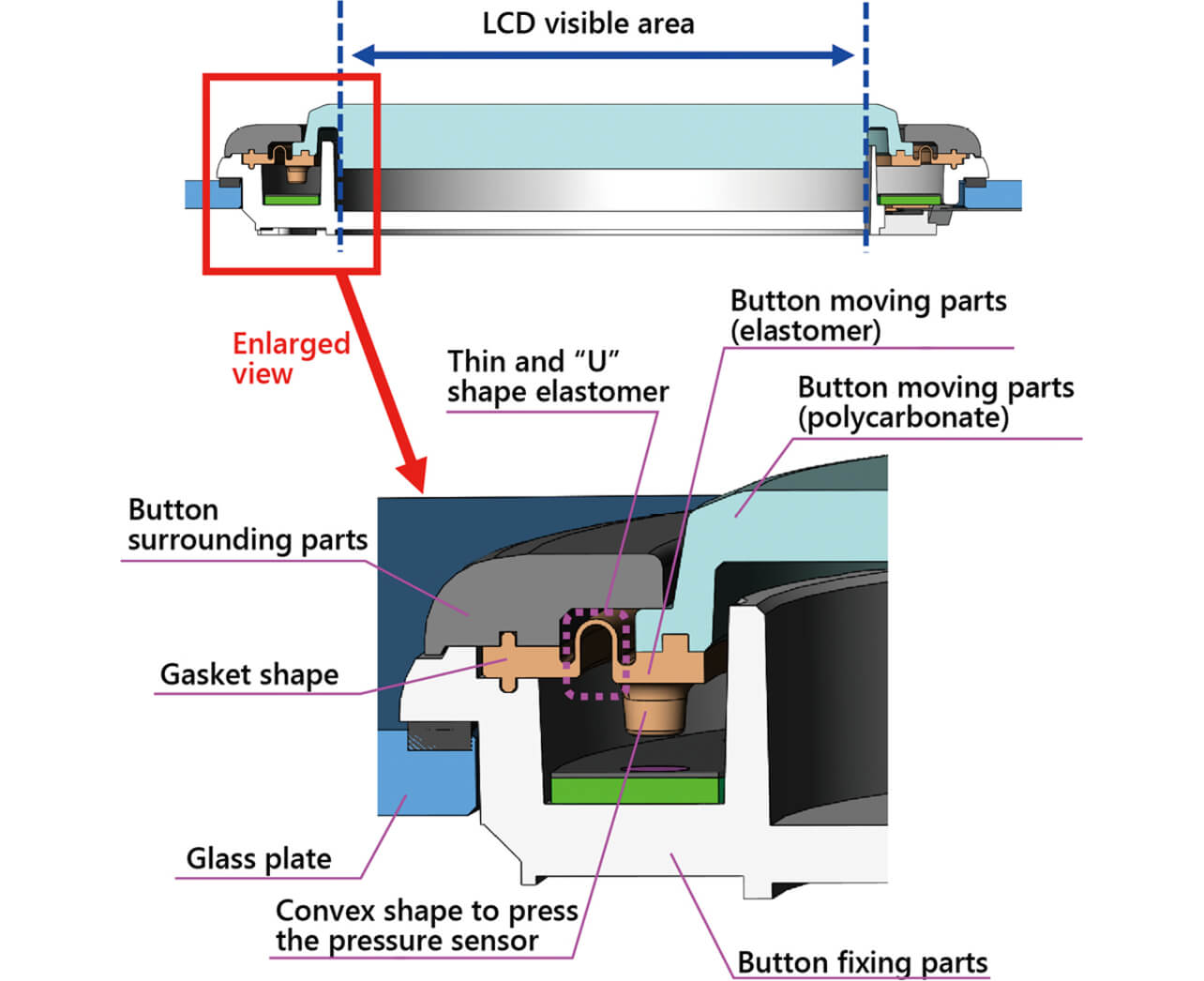
As shown in Fig. 11, the button moving parts are composed of transparent polycarbonate in the range of appearance visible to the player, and other than that, it is composed of an elastomer. A gasket is provided that extends from the button moving parts toward the outside of the product, and the gasket is located between the button surrounding parts and the button fixing parts. This configuration prevents liquid from entering inside the product.
Then, we will describe the measures for the repetitive action of switch operation. As shown in Fig. 11, the elastomer with a thin-wall U-shaped cross-section is provided between the gasket part and the convex shape of the button moving parts. Thus, the elastomer part can divide the vertically moving section and the attachment section. Although this U-shaped elastomer is preferably thin considering the durability of vertical movement, there was the possibility that an excessively thin elastomer could not be molded. For this, a thickness of 0.2 mm was adopted according to flow analysis and product achievement in the past. Consequently, it was successfully verified that the elastomer part was not damaged after conducting durability tests (4 million times or more at pushdown force of 30 N) of switch operation with this structure.
4.3 Realization of structure related to static electricity resistance
This product had the problem that static electricity resistance with sufficient creepage distance could not be secured. There are two ways of securing static electricity resistance. The first is a seal to prevent static electricity from entering inside the product. The second is to provide a part for positively receiving static electricity and connect that part to the ground (GND) of the product. As mentioned in section 4.2, static electricity was considered not to enter inside the product because the water-resistant structure was created by providing gasket parts. However, it was found that static electricity enters the product through a narrow clearance between the fixed part and the gasket made of elastomer, which does not allow liquid to pass through. Therefore, we studied the structure positively receiving static electricity in the product as a basic way of thinking.
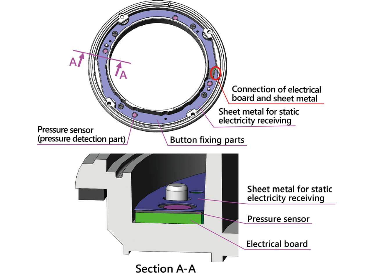
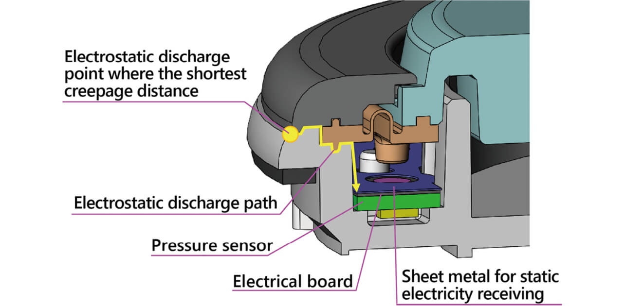
When static electricity enters inside the product, the electrical board for decorative illumination is most easily broken. It is necessary to provide a place for receiving the static electricity before the electricity reaches the electrical board for decorative illumination through the clearance between the button moving parts and the button fixing parts. Therefore, a sheet metal with a thickness of 0.1 mm for receiving static electricity was provided on top of the pressure sensor and was electrically connected to the GND of the electrical board for decorative illumination using electric conductive tape. Fig. 12 shows the top view where the button moving parts and the button surrounding parts are hidden, and the arrangement of the sheet metal for receiving static electricity is presented. The sheet metal is installed so that it covers the pressure sensor and the electrical board for decorative illumination under the sheet metal, and the sheet metal is electrically connected to the GND of the electrical board at the place indicated by a red circle in Fig. 12.
The contact discharge test at ±10 kV and aerial discharge test at ±27 kV verified that the adoption of the product structure shown in Fig. 12 secured the static electricity resistance required for the product shown in Table 2. Fig. 13 shows the path through which the static electricity entered inside the product reaches the sheet metal for receiving static electricity.
4.4 Realization of product appearance
Here the problems were to expand the region of the LCD display part as much as possible, to raise the LCD display to the top of the button, to realize the decorative illumination function emitting light uniformly, and to avoid the harness from attracting attention.
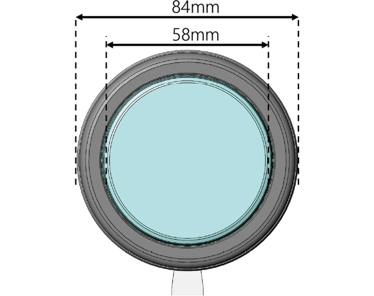
First, the expansion of the region of the LCD display part depends on the structure described in sections 4.1 to 4.3. Consequently, the product externals was 84 mm in diameter, and the LCD display part was 58 mm in diameter. Fig. 14 shows the top view of this product.
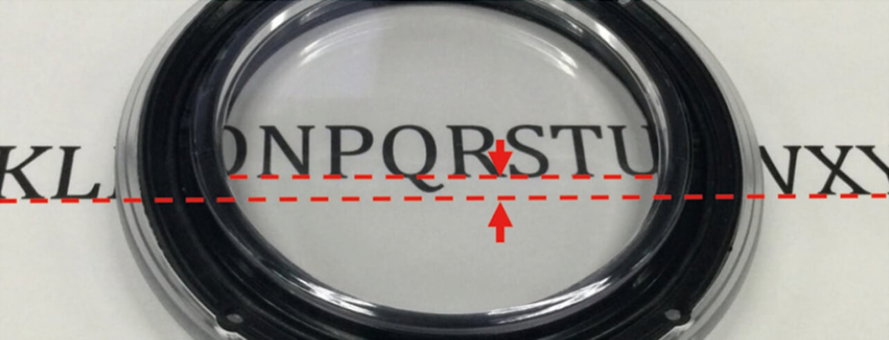
Then, the image displayed on LCD could be raised to the top of the button by adopting thick transparent polycarbonate for the button moving parts, by using the difference between the refractive index in the air and in the transparent polycarbonate. However, as described in section 4.2, the mold temperature cannot be greatly changed between the time of polycarbonate molding and the time of elastomer molding because two-color molding is implemented for the button moving parts, and the cooling time should be the same. Therefore, the restriction in the molding condition is greater than that of single material molding. For such a restriction, an insertion die enabling adjustment of the thickness of the polycarbonate was manufactured, and the thickness that was found in the molding condition suitable for mass production was 7.0 mm. When the thickness is smaller than 7.0 mm, for example, 4.0 mm at the time of trial molding, although polycarbonate can be molded with a cooling time about half that for a thickness of 7.0 mm without deformation, cooling time was short for the elastomer where the shape was greatly deformed, and many burrs were generated. Therefore, the thickness of 7.0 mm was adopted for this product. Fig. 15 shows the view that the image displayed on LCD is raised up by the button moving parts for which thick wall molding of 7.0 mm was implemented.
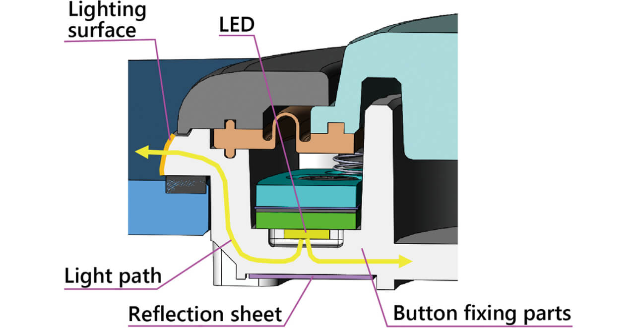
Then, we will describe the decorative illumination emitting light uniformly. As shown in Fig. 8, since the pressure sensor is arranged on the electrical board for the decorative illumination and the moving part of the button is pushed down by the button operation in the space over this, a structure for the decorative illumination cannot be provided. Therefore, we studied whether to arrange a top type LED (light emitting diode) emitting light vertically to the mounted surface under the electrical board for the decorative illumination to pass light through the thick wall of the button fixing parts. Fig. 16 shows the light path passing through the thick wall of the button fixing parts. The light coming out from the LED enters the thick wall of the button fixing parts, and dispersion, reflection, and transparency are generated in every place of the button fixing parts. On the other hand, the lighting surface of the decorative illumination, which is desired to emit light, is located far from the LED light source as shown by the orange color in Fig. 16. Therefore, a reflection sheet was arranged so as to avoid optical attenuation inside the thick wall of the button fixing parts as much as possible as shown in Fig. 16. This method for passing light enabled sufficient dispersion until reaching the lighting surface of the decorative illumination and the acquisition of even light emission on the lighting surface of the decorative illumination.
Furthermore, when a side type LED emitting light horizontally to the mounted surface is used, since the amount of light reflected by the reflection sheet is small, the dispersion inside the thick wall of the button attachment part is weak, and the light emission of the light emitting surface of the decorative illumination was not uniform. Therefore, the side type LED was not adopted.
Although the combination of the top type LED and the reflection sheet arranged at the opposite side of the lighting surface obtained uniform light emission of the lighting surface of the decorative illumination, since the light from LED advances inside the button fixing parts allowing the light from the LED to be seen on the LCD display part. Therefore, we decided that the button fixing parts are also created by two-color molding as same as the button moving parts and black resin is partially used in order to shield the light from the LED. Fig. 17 shows the light path passing through the thick wall of the button fixing parts created by two-color molding.
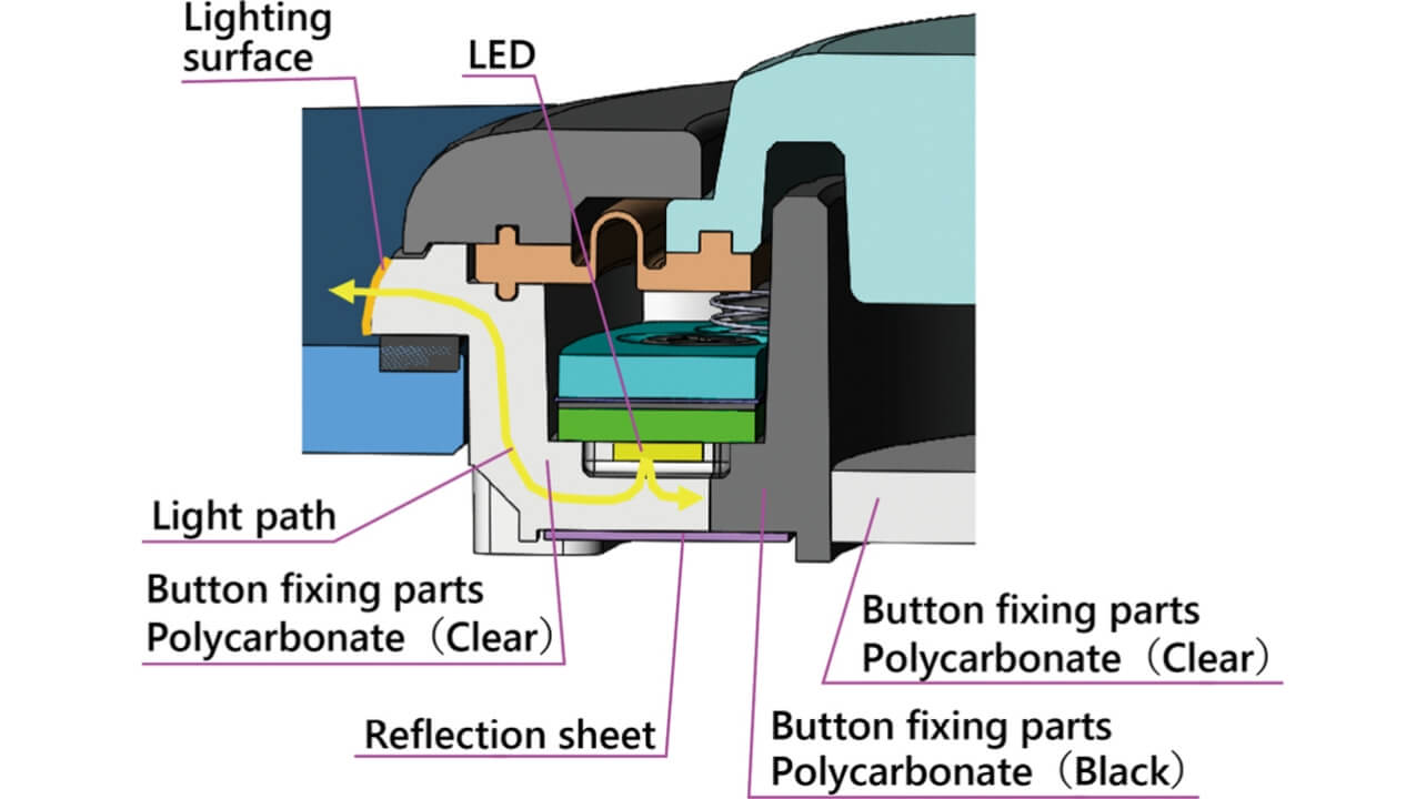
Polycarbonate was selected for the button fixing parts considering shock resistance as described in section 4.1. We adopted polycarbonate of a different grade as the material for two-color molding. The one we selected was transparent polycarbonate, and the other was black and sliding grade polycarbonate. Sliding grade was used for the black part because the part serves as a stopper for the button moving parts and is the place for sliding. The adoption of such a structure for the button fixing parts enabled one part to serve both as the decorative illumination function and the sliding structure. Fig. 18 shows the photograph of the actual light emission of the decorative illumination.
We will describe the method for making the harness not noticeable at the end of this section. The harness requires a power supply line for decorative illumination, its signal line, and a power supply line for the pressure sensor and signal line. Since the pressure sensor has a sheet-like shape, the harness part can be added to the pressure sensor shown in Fig. 7. Although the transparent base material can be used for the pressure sensor, the thick wiring part is noticeable because it cannot be made transparent. Fig. 19 shows the photograph of the pressure sensor using a transparent base material on the LCD.

This photograph shows that the presence of wiring has great effects. On the other hand, the electrical board for decorative illumination can be loaded with a connector for the FPC (flexible printed circuits) and can utilize the transparent FPC of the transparent polyimide base material. Fig. 20 shows the photograph of the transparent FPC put on the LCD.
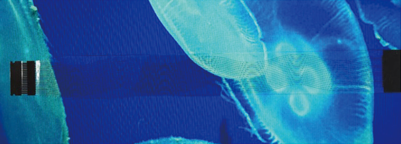
It is found that wiring is not more noticeable than the transparent pressure sensor shown in Fig. 19. The reason why the wiring has a wave pattern here is to restrict the moiré with the pixels of the LCD. Considering the above, we studied how to make the presence of the harness not noticeable by using only one transparent FPC as the harness for this product.
However, in order to use the harness of only the transparent FPC, the electrical connection of the pressure sensor and the electrical board for decorative illumination inside the product is required. Usually the method of using an FPC connector is general for such an electrical connection. However, the FPC connector could not be installed because the space for this product is very limited as stated so far. Therefore, the technique of ACF (anisotropic conductive film) crimping the sheet-like pressure sensor and electrical board for decorative illumination that is often used for connection of a multipole, such as an LCD, was employed. Fig. 21 shows the actual photograph after ACF crimping.
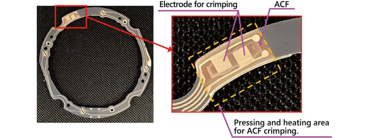
Since the pressure sensor has the signal line of only two poles as shown in the electrode for crimping, the electrode size was decided to be approx. 3 mm × 3 mm. As afore-mentioned, since the ACF crimping is often used for the narrow pitch and multipole connection of an LCD of about 0.5 mm, the size of the electrode for crimping used for this product belongs to a very large group. Such enlargement of the electrode size secures the adhesion of the ACF crimping and prevents the pressure joined part from peeling off even if large shock and large vibration are added to this product. Thus, the ACF crimping enabled the reasonable achievement of the electrical joining of the pressure sensor and the electrical board for decorative illumination and to use only the transparent FPC as the harness for this product.
5. Conclusions
Although casino machines with a future feeling attracting players evolved in recent years, the SPIN button was delayed from this trend. This time, as one of the methods for attracting players, we designed the thin type push button capable of contributing to the realization of the direction of the casino machine never seen before with a transmissible LCD display underneath the button, and commercialized it as our product after verifying that it passed all the various product test items, such as the test for checking the basic function as the button as shown in Table 2 and the water resistant test. Fig. 22 shows the appearance photograph of this product.
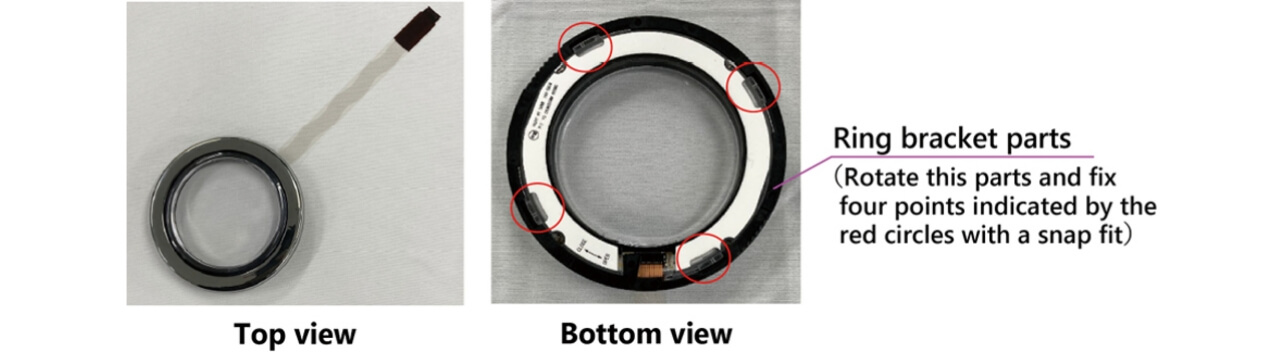
The size of the product is 84 mm in diameter and 14.2 mm in height, and the size of the LCD display and transparent section is 58 mm in diameter. Furthermore, the product is installed using the ring part for fixing as supplied with the product and can be attached without using any tools.
In addition, Fig. 23 shows the appearance of photograph of the prototype of the casino machine operation button section created to introduce this product.
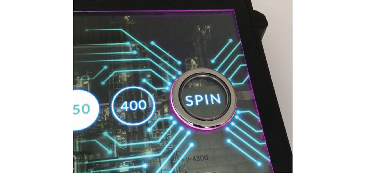
This is a photograph of the realized Plan 2 in Fig. 4. Many complicated problems were intertwined into the realization or commercialization of a product like this, but we successfully realized a product matching the needs of the industry by providing multiple functions of giving two or three roles to one part as the solution for each item.
Although this product is a general-purpose one where development was promoted targeting the casino machine industry, this product can be installed only if the structure in which a glass plate is placed on the LCD exists even in an industry other than casino machines. For example, the application to digital signage often seen in railroad stations or commercial facilities in recent years can be cited. Hereafter, we wish to promote the deployment of this product so as to be able to deal with industries other than casino machines as mentioned above.
In addition, as a technical perspective in the future, we wish to promote studies of the further reduction in button height from the glass surface and a change to narrower bezel of a button (button fixing parts shown in Fig. 11).
References
- 1)
- OMRON Corporation, “Reference Materials for Microswitches,” https://www.fa.omron.co.jp/guide/technicalguide/29/326/index.html, (accessed April 12, 2021).
The names of products in the text may be trademarks of each company.